Application method of control system for precisely measuring abbe errors
A precision measurement and Abbe error technology, applied in the direction of measuring devices, optical devices, instruments, etc., can solve the problems of low measurement accuracy and achieve the effects of improving accuracy, adjusting level, and facilitating disassembly and storage
- Summary
- Abstract
- Description
- Claims
- Application Information
AI Technical Summary
Problems solved by technology
Method used
Image
Examples
Embodiment 1
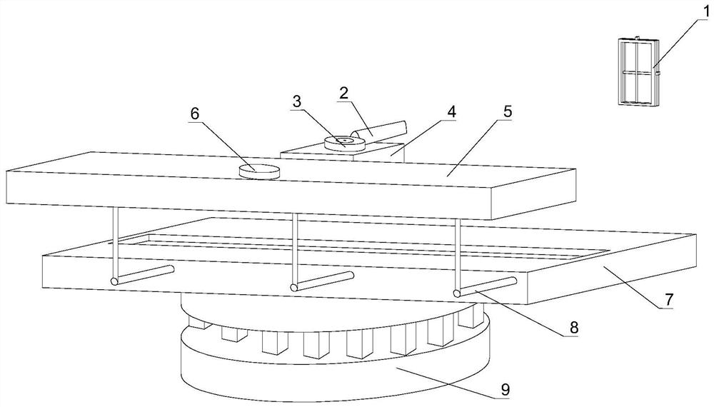
[0038] like figure 1 As shown, the present embodiment relates to a method for using a precision measurement Abbe error control system, including the following steps:
[0039] S1: Install the laser precision measuring instrument in the precision measurement Abbe error control system, adjust the horizontal height of the measurement axis of the laser precision measurement instrument to be on the same level as the motion axis of the workpiece to be tested; the precision measurement Abbe error control system includes A cross locator 1 and a laser transmitter 2, the cross locator 1 is provided with a cross positioning point, the cross positioning point corresponds to the position of the launch port of the laser transmitter 2, and a fixing seat is fixed below the laser transmitter 2 4. A horizontal indicator 3 is fixed on the top of the fixed seat 4, and a fine-tuning plate 5 is provided on the side of the fixed seat 4 facing away from the launch port of the laser transmitter 2, and ...
Embodiment 2
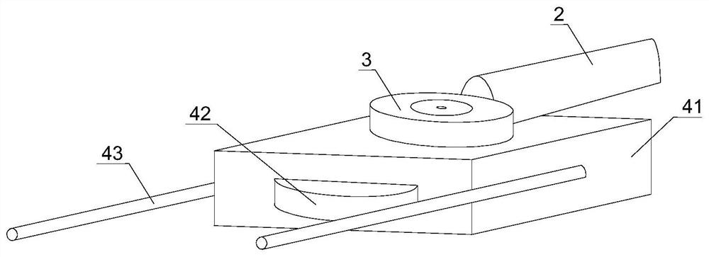
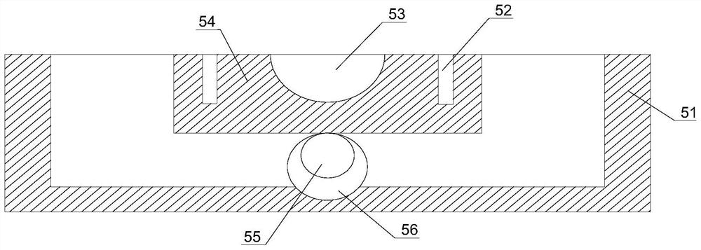
[0049] like Figure 1~4 As shown, on the basis of Embodiment 1, the fixed seat 4 specifically involved in this embodiment includes a seat body 41, and a number of limit rods 43 are fixed on both sides of the seat body 41, and the limit rods 43 are emitted by laser light. The device 2 is centrally symmetrical and evenly distributed, and the side of the base body 41 facing away from the laser emitter 2 is fixed with a semicircular plate 42, and the semicircular plate 42 and the limit rod 43 are embedded in the fine-tuning plate 5, and the knob 6 can be placed on the fine-tuning plate 5, adjust the lateral movement of the semicircular plate 42 and the limit rod 43; the fine-tuning plate 5 includes a plate body 51, and a moving block 54 is provided on the side of the plate body 51 close to the fixed seat 4, and the moving block 54 is embedded in the plate body 51 , and the upper surface of the moving block 54 is fixed with a limit plate 58, and the contact surface between the plat...
Embodiment 3
[0052] like Figure 1-7As shown, the difference between this embodiment and Embodiments 1 and 2 is that the horizontal adjustment seat 9 includes a horizontal top plate 91, the upper surface of the horizontal top plate 91 is fixed to the support seat 7, and a connecting seat is provided below the horizontal top plate 91. 93, between the connection seat 93 and the horizontal top plate 91, several telescopic adjustment rods 92 are evenly distributed in the circumferential direction, the upper end of the telescopic adjustment rod 92 is fixed with the horizontal top plate 91, and its lower end is fixed with the connection seat 93; the horizontal top plate 91 includes The top shell 911 is provided with a circular hydraulic chamber 913 inside the top shell 911, the hydraulic chamber 913 is filled with hydraulic oil 912, the hydraulic chamber 913 is fixed to the inner wall of the top shell 911, and there are several number And the pressure sensor 915 whose position corresponds to the...
PUM
 Abstract
Description
Claims
Application Information
 - R&D
- Intellectual Property
- Life Sciences
- Materials
- Tech Scout
- Unparalleled Data Quality
- Higher Quality Content
- 60% Fewer Hallucinations
Browse by: Latest US Patents, China's latest patents, Technical Efficacy Thesaurus, Application Domain, Technology Topic, Popular Technical Reports.
© 2025 PatSnap. All rights reserved.Legal|Privacy policy|Modern Slavery Act Transparency Statement|Sitemap|About US| Contact US: help@patsnap.com


