
Compensator component device for energy accumulator

A compensator and accumulator technology, applied in the field of compensators, can solve the problems of acid resistance, general sealing, and low life, and achieve the effect of good sealing and maximized space

Inactive Publication Date: 2020-12-11
ANHUI WEIMAI OME SCI & TECH CO LTD
View PDF13 Cites 0 Cited by
  • Summary
  • Abstract
  • Description
  • Claims
  • Application Information

AI Technical Summary

Problems solved by technology

The structure of the traditional accumulator device, when used, the compensator is installed inside the accumulator, and there is a shell with a specific structure outside, and the accumulator is installed at a certain position in the pipeline, and its interior is usually a piston or an air bag The piston type accumulator is not sensitive enough to compensate quickly; the airbag type accumulator is sensitive to compensation but has a low service life, general sealing performance, and is not resistant to acid, alkali and other corrosion scenarios

Method used


Image

  • Compensator component device for energy accumulator
  • Compensator component device for energy accumulator
  • Compensator component device for energy accumulator

Examples


Embodiment Construction

[0015] The following will clearly and completely describe the technical solutions in the embodiments of the present invention with reference to the accompanying drawings in the embodiments of the present invention. Obviously, the described embodiments are only some, not all, embodiments of the present invention. Based on the embodiments of the present invention, all other embodiments obtained by persons of ordinary skill in the art without making creative efforts belong to the protection scope of the present invention.

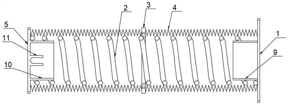
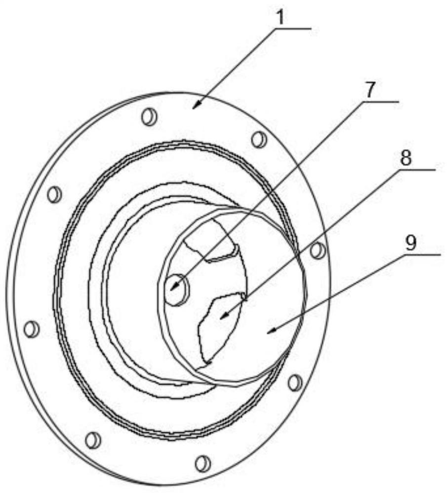
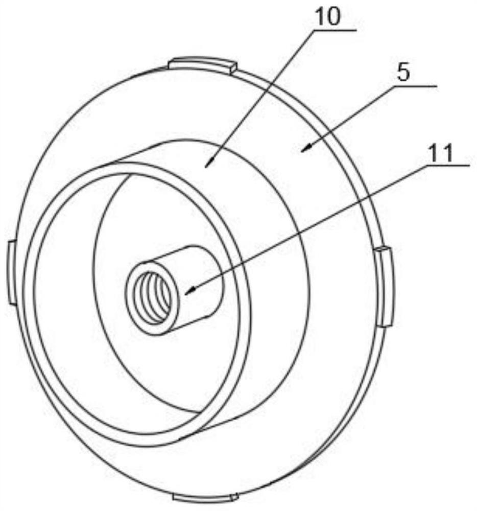
[0016] Such as Figure 1-4 A compensator assembly device for an accumulator is shown, including a front flange 1, a spring 2, a middle guide 3, a compensator shrapnel group 4 and a rear end flange 5, and the compensator shrapnel group 4 is composed of a plurality of corrugated membranes Its elasticity is provided by the corrugated diaphragm device, the length is scalable, and the overall shape is bellows. Among them, the corrugated diaphragm is made of solid s...


PUM


Abstract

The invention discloses a compensator component device for an energy accumulator, and particularly relates to the field of compensators. The compensator component device comprises a front end flange,a spring, a middle guider, a compensator elastic sheet group and a rear end flange; the compensator elastic sheet group is formed by welding a plurality of corrugated membranes; the elasticity of thecompensator elastic sheet group is provided by a corrugated membrane device; the compensator elastic sheet group is telescopic in length and is integrally in a corrugated pipe shape; the spring is located in the compensator elastic sheet group; the middle guider is located at the middle point in the transverse direction of a metal elastic sheet group; the compensator elastic sheet group is dividedinto a left section and a right section which are the same; and metal elastic sheets in the two sections of compensator elastic sheet group are fixedly connected to the two sidewalls of the middle guider respectively. The compensator component device disclosed by the invention is good in sealing performance; the sealing part is resistant to acid and alkali corrosion, high temperature and low temperature; during compression or extension work, the motion linearity of the compensator component device can be well calculated; compared with a bag type energy accumulator of a conventional structure,the compensator component device can bear relatively high pressure, and the sealing structure is cylindrical, so the installation space can be fully and effectively utilized for design, and space maximization is achieved.

Description

technical field [0001] The invention relates to the field of compensators, and more specifically, the invention relates to a compensator assembly device for an accumulator. Background technique [0002] During the transportation process of temperature-changing medium from -55°C to 200°C, the pipeline will expand with heat and contract with cold due to the change of medium temperature, which will cause the change of liquid pressure and liquid volume inside the pipeline, usually at An accumulator device is installed on the pipeline. The structure of the traditional accumulator device, when used, the compensator is installed inside the accumulator, and there is a shell with a specific structure outside, and the accumulator is installed at a certain position in the pipeline, and its interior is usually a piston or an air bag The piston-type accumulator is not sensitive enough to compensate quickly; the airbag-type accumulator is sensitive to compensation but has a low service l...

Claims


Application Information

Patent Timeline
Patent Type & Authority Applications(China)
IPC IPC(8): F16L51/02F16L55/02
CPCF16L51/02F16L55/02
Inventor 王伟蒋云龙吴波
Owner ANHUI WEIMAI OME SCI & TECH CO LTD
Learn More