
Feeding device for hot process regeneration equipment

A feeding device, thermal regeneration technology, applied in packaging, loading/unloading, transportation and packaging, etc., can solve problems such as inability to stably feed, inability to automatically feed, etc.

Inactive Publication Date: 2020-12-11
KOCEL EQUIP
View PDF6 Cites 0 Cited by
  • Summary
  • Abstract
  • Description
  • Claims
  • Application Information

AI Technical Summary

Problems solved by technology

[0003] The invention overcomes the problem that the existing thermal regeneration equipment cannot feed stably and automatically in the case of high impurities and large particles, and provides a stable feeding method suitable for thermal regeneration equipment in the case of high impurities and large particles. The fully automatic control device of the material realizes the effect of automatically controlling the feeding and stabilizing the feeding

Method used


Image

  • Feeding device for hot process regeneration equipment
  • Feeding device for hot process regeneration equipment
  • Feeding device for hot process regeneration equipment

Examples


Embodiment 1

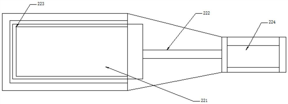
[0019] The present invention provides a fully automatic control device suitable for thermal regeneration in the case of high impurities and large particles, which includes a material storage warehouse 100, an automatic slide valve 200, a flexible star unloader 300, an automatic Control cabinet 400.

[0020] The automatic gate valve 200 is located under the material storage warehouse 100, and can automatically control the size of the outflow of materials from the material storage warehouse. The flexible star unloader 300 is located under the automatic gate valve 200, which can realize the material discharging speed and the material discharge rate. The amount of control, the automatic control cabinet 400 can realize the real-time interlocking of the thermal regeneration equipment and the automatic control of the automatic slide valve 200 and the flexible star unloader 300 according to the demand of the thermal regeneration material, so as to realize the high impurity of the mater...

Embodiment 2

[0026]The automatic control cabinet 400 is connected upwards to the thermal regeneration equipment, including the manual knob 410 for the opening of the gate valve, the rotation speed adjustment knob 420, the display screen 430, the connection line for the automatic gate valve 440, the connection line for the flexible star unloader 441, the thermal French connecting line 442. The automatic control cabinet 400 obtains the real-time material demand, connects the automatic gate valve and the flexible star unloader through the automatic gate valve connecting line 440 and the flexible star unloader connecting line 441 respectively, and connects through the thermal method connecting line 442 Thermal regeneration equipment. The automatic control cabinet 400 is used to control the interlocking of thermal regeneration equipment and the automatic gate valve and flexible star unloader, so that the automatic gate valve and flexible star unloader can be realized in real time according to t...


PUM


Abstract

The invention relates to a full-automatic control device for hot process regeneration equipment. The device comprises a material storage tank, an automatic gate valve, a flexible star-type unloader and an automatic control cabinet. The automatic gate valve is connected below the material storage tank, the flexible star-type unloader is connected below the automatic gate valve, and the automatic control cabinet is connected to the automatic gate valve and the flexible star-type unloader. The device overcomes the problem that existing hot process regeneration equipment cannot feed materials stably under circumstances of high purities and large particles and cannot feed the materials automatically, plays roles of controlling feeding automatically and feeding the materials stably still under the circumstance of high impurity particles of the materials, and has the functions of controlling feeding automatically and controlling stable feeding to achieve full-automatic precise quantitative and continuous stable feeding by hot process regeneration.

Description

technical field [0001] The invention relates to a fully automatic feed control device, especially suitable for a fully automatic feed control device for thermal regeneration equipment. Background technique [0002] At present, the feeding device of the thermal regeneration equipment uses a material storage warehouse and a manual flapper valve to control the size of the material entering the thermal regeneration. This method can only control the size of the material by manually adjusting the size of the flapper valve gap. When When the material contains high impurities and large particles, it is easy to block the gap of the gate valve, and the material cannot enter the thermal regeneration process, and cannot automatically feed the material according to the real-time demand for thermal regeneration, resulting in empty thermal regeneration. The burning phenomenon will cause damage to the thermal regeneration. Contents of the invention [0003] The invention overcomes the pr...

Claims


Application Information

Patent Timeline
IPC IPC(8): B65G65/48B65D88/28
CPCB65D88/28B65G65/48
Inventor 李军李培亮杜海平郭亮岳忠磊
Owner KOCEL EQUIP
Learn More