
Loading auxiliary device for auto plastic part processing

A technology of plastic parts and auxiliary devices, applied in the field of automobile plastic parts feeding equipment, can solve the problems of complicated operation, low feeding efficiency, low working efficiency, etc., to achieve expansion, facilitate feeding, and improve feeding efficiency. Effect

Active Publication Date: 2020-12-11
阜南县艺达工艺品有限公司
View PDF5 Cites 2 Cited by
  • Summary
  • Abstract
  • Description
  • Claims
  • Application Information

AI Technical Summary

Problems solved by technology

[0004] The purpose of the present invention is to provide a feeding auxiliary device for the processing of automobile plastic parts, to solve the problem that when the existing automobile plastic parts are processed and assembled with O-rings, workers need to pick up the O-rings one by one, which cannot be automatically loaded, and the operation is relatively difficult. It is cumbersome, and the feeding efficiency is low; when the existing automobile plastic parts are processed and assembled with O-rings, there is no expansion step of O-rings, which is not convenient to be placed on the plastic parts, and manual expansion of O-rings is difficult, time-consuming and laborious; When some automotive plastic parts are processed and assembled with O-rings, it is difficult to insert the plastic parts directly into the O-rings, the labor intensity of the workers is high, and the work efficiency is low.

Method used


Image

  • Loading auxiliary device for auto plastic part processing
  • Loading auxiliary device for auto plastic part processing
  • Loading auxiliary device for auto plastic part processing

Examples


Embodiment Construction

[0032] The technical solutions of the present invention will be clearly and completely described below in conjunction with the embodiments. Apparently, the described embodiments are only some of the embodiments of the present invention, not all of them. Based on the embodiments of the present invention, all other embodiments obtained by persons of ordinary skill in the art without creative efforts fall within the protection scope of the present invention.

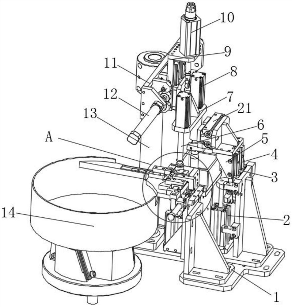
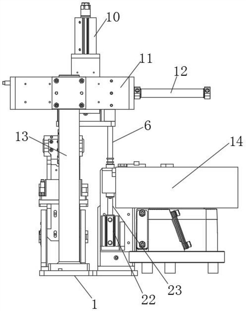
[0033] Such as Figure 1-8 As shown, a feeding auxiliary device for the processing of automobile plastic parts includes a base plate 1 and a support column 13. Three support frames 24 are arranged on the top of the base plate 1, and a vibrating plate 14 is arranged on one side of the base plate 1, which is located on the vibrating plate. A third hydraulic cylinder 15 is fixedly arranged at the top position of one side of the side wall of the support frame 24 on one side of 14, and one end of the third piston rod inside the th...


PUM


Abstract

The invention discloses a loading auxiliary device for auto plastic part processing. The loading auxiliary device for auto plastic part processing comprises a bottom plate and a supporting column. Three supporting racks are arranged on the top of the bottom plate, a vibration plate is arranged on one side of the bottom plate, a third hydraulic cylinder is fixedly arranged on the top of the side wall of one side of the supporting rack located on the side of the vibration plate, one end of a third piston rod in the third hydraulic cylinder is fixedly connected to a right-angled bracket, a thirdslide block is fixedly arranged at one end of the right-angled bracket, a loading seat is controlled by a second hydraulic cylinder to move downward, and meanwhile, a loading rod is controlled by a loading hydraulic cylinder to move toward a cylinder block. As the second hydraulic cylinder is matched with the loading hydraulic cylinder, the bottom end of a plastic part is in contact with the top end of an expansion rod. A first lifting plate is controlled by the first hydraulic cylinder to move upward, an O-shaped ring is moved to the plastic part to load the O-shaped ring, so that the problemthat it is hard to sleeve the plastic part into the O-shaped ring directly is solved, the labor intensity of a worker is reduced and the work efficiency is improved.

Description

technical field [0001] The invention relates to the field of feeding equipment for automobile plastic parts, in particular to a feeding auxiliary device for processing plastic parts of automobiles. Background technique [0002] There are many types of automotive plastic parts, such as tubular, square, etc. When processing and assembling tubular plastic parts, the assembly of O-rings is included. [0003] When processing and assembling O-rings for existing automotive plastic parts, workers need to take the O-rings one by one, which cannot be automatically loaded, and the operation is cumbersome and the loading efficiency is low; Without the expansion step of O-ring, it is not convenient to fit on the plastic parts, and the manual expansion of O-ring is difficult, time-consuming and laborious; when the existing automotive plastic parts are processed and assembled with O-rings, the plastic parts are directly inserted into the O-rings Difficulty, the labor intensity of the work...

Claims


Application Information

Patent Timeline
Patent Type & Authority Applications(China)
IPC IPC(8): B29C65/56
CPCB29C65/56Y02W30/62
Inventor 马之强李文秀马小龙马之虎
Owner 阜南县艺达工艺品有限公司
Learn More