Novel hydraulic and pneumatic composite control cylinder of hydraulic hammer and sealing form

A hydro-pneumatic and composite control technology, which can be used in fluid pressure actuating devices, sheet pile walls, buildings, etc., and can solve the problems of large volume and weight of pile hammers.

Inactive Publication Date: 2020-12-08
ZHEJIANG YONGAN CONSTR MASCH CO LTD +1
View PDF14 Cites 2 Cited by
  • Summary
  • Abstract
  • Description
  • Claims
  • Application Information

AI Technical Summary

Problems solved by technology

[0006] The main purpose of the present invention is to provide a new hydraulic hammer hydraulic-pneumatic composite control cylinder and sealing form to realize the combination of the hydraulic and pneumatic systems of the piling hammer, and to solve the problem of excessive volume and weight of the piling hammer due to the complex structure of the cylinder body

Method used


Image

  • Novel hydraulic and pneumatic composite control cylinder of hydraulic hammer and sealing form
  • Novel hydraulic and pneumatic composite control cylinder of hydraulic hammer and sealing form
  • Novel hydraulic and pneumatic composite control cylinder of hydraulic hammer and sealing form

Examples


Embodiment Construction

[0021] The present invention will be further described below in conjunction with the embodiments described in the accompanying drawings.

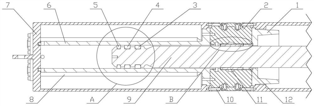
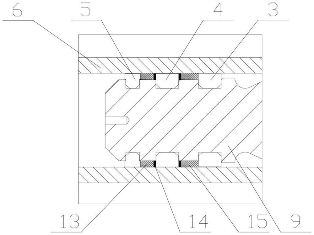
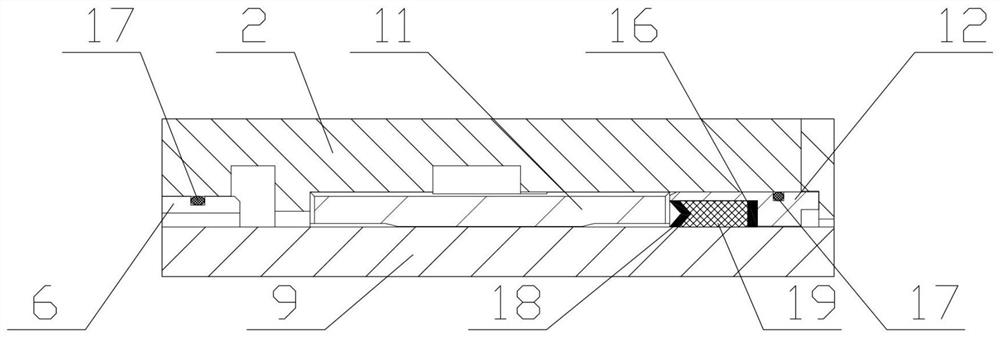
[0022] figure 1 It is a structural schematic diagram of the main part of an embodiment of the present invention. As shown in the figure, the new hydraulic hammer hydraulic pneumatic compound control cylinder and sealing form of the present invention structurally include a top stroke limiter 1, an integrated combined valve block 2, a piston ring 3, a compression ring 4, a fixed ring 5, and a cylinder body ( Integrated hydraulic and pneumatic composite control cylinder) 6, outer shell 7, accumulator 8, piston rod 9, socket head screw 10, piston rod bearing bush 11, piston rod sealing box 12. Piston rod 9 is connected with the hammer body of piling hammer.

[0023] The integrated hydraulic-pneumatic compound control cylinder is the key part of the hydraulic-pneumatic compound piling hammer. The sealed space between the cylinder body 6 and t...


PUM


Abstract

The invention provides a novel hydraulic and pneumatic composite control cylinder of a hydraulic hammer and a sealing form. The integrated hydraulic and pneumatic composite control cylinder is formedby a piston rod, a piston, an air-tight sealing piece, a liquid sealing piece and a cylinder body, and reciprocating movement and hammering of a pile hammer are achieved through hydraulic force, aerodynamic force and hammer core gravity. The integrated hydraulic and pneumatic composite control cylinder is compact in structure, a cylinder is composed of a shell, a high-pressure energy accumulator,a low-pressure energy accumulator and a closed space between cylinder bodies, the space in the hydraulic hammer is fully utilized, and the structural complexity caused by the fact that cylinder components are additionally arranged in the hammer is reduced. A gas-liquid combined sealing mode is adopted at the piston end, three sets of split mounting type rings, gas sealing pieces, oil sealing pieces etc. are included, the gas sealing pieces and the hydraulic sealing pieces are respectively arranged at two sides with a compression ring as the center, the outermost layer is provided with one setof ring for bearing most oil pressure and air pressure, the bearing capacity of the sealing pieces is reduced, and gas-liquid separation is achieved. By adopting the structure, the complexity of an air-tight sealing structure and an oil sealing structure at the piston can be reduced, and then the combination of hydraulic and pneumatic systems of the pile hammer is realized. A totally-enclosed structure and a piston rod guide mechanism are adopted, and the structure can be used for inclined pile driving and underwater operation.

Description

technical field [0001] The invention belongs to the field of mechanical engineering and civil engineering engineering machinery piling machinery, mechanical parts and transmission devices, and in particular relates to a mechanical structure and equipment of a hydraulic-pneumatic composite piling hammer. Background technique [0002] Compared with the hydraulic hammer, which has been developed rapidly in recent years, the traditional piling hammer represented by diesel hammer has shortcomings in environmental pollution control, piling efficiency, and striking energy, while hydraulic piling hammer has high piling efficiency, low noise and vibration. Small size, no oil fume pollution and other characteristics, its advanced nature has been widely recognized, the hydraulic piling hammer will replace the original traditional diesel hammer, and become the absolute main force in the piling market. [0003] The integrated hydraulic-pneumatic composite control cylinder of the double...

Claims


Application Information

Patent Timeline
IPC IPC(8): F15B15/14F15B15/20F15B15/24E02D7/06E02D7/14
CPCF15B15/1423F15B15/1428F15B15/1452F15B15/1457F15B15/1461F15B15/1471F15B15/149F15B15/202F15B15/24E02D7/06E02D7/14
Inventor 林登訚耀保郭传新郑毓鹏
Owner ZHEJIANG YONGAN CONSTR MASCH CO LTD
Why Eureka
Try Eureka