
Electrophoretic coating system

A coating system and electrophoretic coating technology, applied in the direction of electrophoretic coating, electrolytic coating, coating, etc., can solve the problems that affect the efficiency and effect of electrophoretic coating of workpieces, insufficient mechanization degree, and insufficient compact structure, etc., to improve market competition Power, safe and convenient to use, and the effect of improving efficiency

Inactive Publication Date: 2020-12-08
梁超雄
View PDF8 Cites 0 Cited by
  • Summary
  • Abstract
  • Description
  • Claims
  • Application Information

AI Technical Summary

Problems solved by technology

[0003] Before the electrophoretic coating, the workpiece often needs to go through pretreatment processes such as degreasing and rust removal to ensure that the surface of the workpiece meets the standards during electrophoresis. Electrophoretic coating method When the workpiece is electrophoretic coated, the workpiece will be directly taken out for drying after electrophoresis in the electrophoresis tank. The drying chamber and the electrophoresis tank are separated and independent. The required distance is longer, and dust fibers are easily attached to the surface, which leads to poor electrophoretic coating effect of the workpiece, which easily leads to an increase in the rejection rate of the electrophoretic coating of the workpiece, and affects the efficiency and effect of the electrophoretic coating of the workpiece.

Method used


Image

  • Electrophoretic coating system
  • Electrophoretic coating system
  • Electrophoretic coating system

Examples


Embodiment

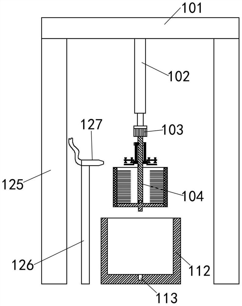
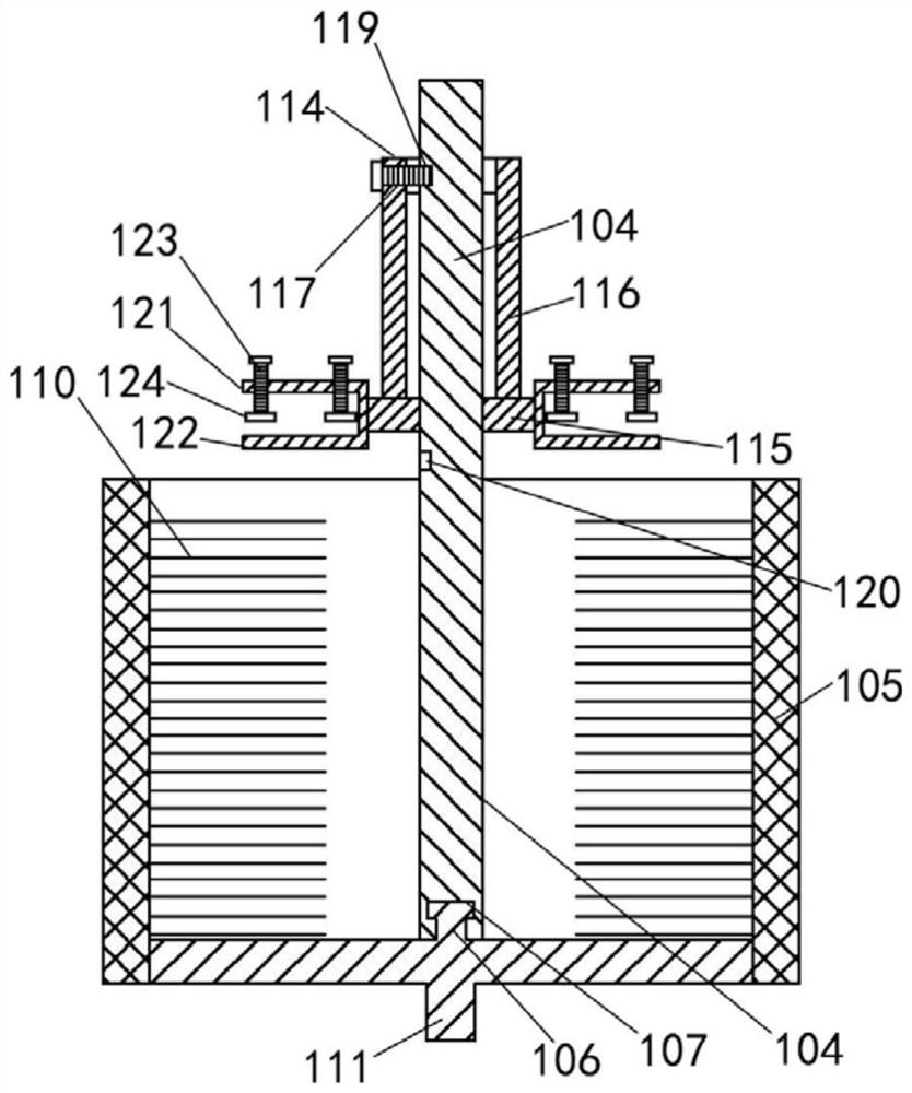
[0047] Example: such as Figure 1-7 An electrophoretic coating coating system shown includes a derusting device 100 and an electrophoretic device 200. After the workpiece is degreased, derusted, phosphating and passivated, it enters the electrophoretic tank 3 of the electrophoretic device 200 for electrophoretic coating , wherein the rust removal of the workpiece is carried out in the rust removal device 100, the rust removal device 100 includes a mounting rod 101, the lower end of the mounting rod 101 is fixed with a pneumatic telescopic rod 102, and the lower end of the rod body of the pneumatic telescopic rod 102 is fixedly connected with a rotating motor 103, and the rotating motor The rotating shaft 104 extends into the metal mesh cylinder 105, and the center of the bottom plate of the metal mesh cylinder 105 is fixed with a positioning convex edge 107 through a connecting rod 106. The connecting rod 106 and the positioning convex edge 107 are inserted into the connecting ...


PUM


Abstract

The invention discloses an electrophoretic coating system. The electrophoretic coating system comprises a rust removal device and an electrophoresis device, wherein the rust removal device comprises amounting rod, and a pneumatic telescopic rod is fixed to the lower end of the mounting rod; the lower end of a rod body of the pneumatic telescopic rod is fixedly connected with a rotating motor, anda rotating shaft of the rotating motor extends into a metal net cylinder; the center of a bottom plate of the metal net cylinder is fixedly connected with a positioning protruding edge through a connecting rod, and the connecting rod and the positioning protruding edge are inserted into a connecting groove and a positioning groove in the bottom end of an output shaft; a plurality of brush wires are fixedly connected to the inner wall of the metal net cylinder, and a fixing block with a rectangular section is fixedly connected to the lower end of a bottom plate of the metal net cylinder and used for being inserted into a fixing hole of a rust removal liquid cylinder; the section of the fixing hole is rectangular, and the rust removal liquid cylinder is filled with rust removal liquid; therotating shaft of the rotating motor is sleeved with an upper lantern ring and a lower lantern ring, and clamping devices are welded to the two sides of the lower lantern ring; and each clamping device comprises a mounting plate and a lower clamping plate, each mounting plate is screwed by at least two screws in a threaded mode, and the lower end of each screw is fixedly connected with an upper clamping plate.

Description

technical field [0001] The invention relates to the technical field of electrophoretic coating, in particular to an electrophoretic coating coating system. Background technique [0002] Electrophoretic coating is a coating method that uses an external electric field to make the particles such as pigments and resins suspended in the electrophoretic liquid directional migrate and deposit on the substrate surface of one of the electrodes. The principle of electrophoretic coating was invented in the late 1930s, but it was developed This technology was applied in industry after 1963. Electrophoretic coating is a special coating film formation method developed in the past 30 years. It is the most practical construction process for water-based coatings. It is water-soluble, non-toxic, Easy automatic control and other characteristics, it has been widely used in industries such as automobiles, building materials, hardware, and home appliances; [0003] Before the electrophoretic coa...

Claims


Application Information

Patent Timeline
Patent Type & Authority Applications(China)
IPC IPC(8): C25D13/22C25D13/20C25D13/24B08B9/087F26B23/00F26B25/00
CPCC25D13/22C25D13/20C25D13/24B08B9/087F26B23/00F26B25/007
Inventor 不公告发明人
Owner 梁超雄
Learn More