
Workpiece conveying system

A conveying system and workpiece technology, which is applied to conveyor objects, transportation and packaging, etc., can solve the problem of manual arrangement of workpieces, such as large labor, and achieve the effects of high reliability, improved material storage capacity, and convenient storage.

Inactive Publication Date: 2020-12-08
温岭市微米自动化设备有限公司
View PDF7 Cites 1 Cited by
  • Summary
  • Abstract
  • Description
  • Claims
  • Application Information

AI Technical Summary

Problems solved by technology

[0004] In order to solve the problem of a large amount of labor in manually arranging workpieces after processing, this application provides a workpiece conveying system

Method used


Image

  • Workpiece conveying system
  • Workpiece conveying system
  • Workpiece conveying system

Examples


Embodiment Construction

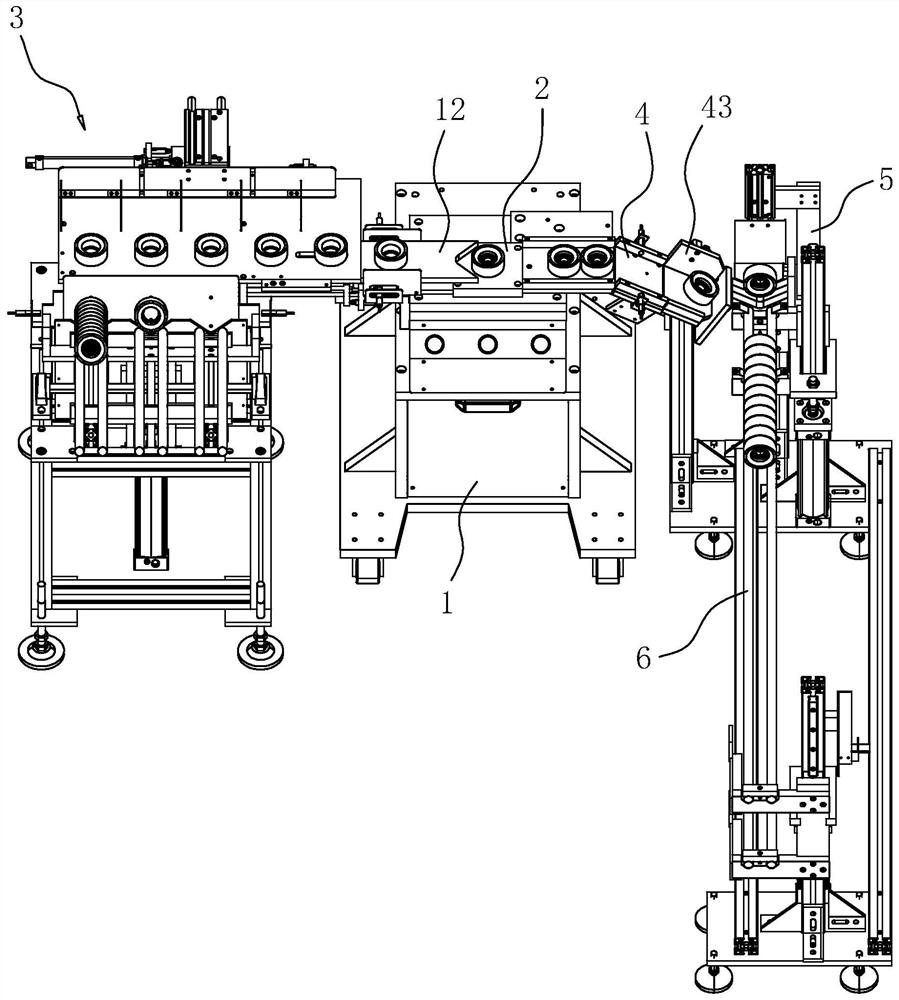
[0036] The following is attached Figure 1-6 The application is described in further detail.

[0037] The embodiment of the present application discloses a workpiece conveying system. refer to figure 1 , the workpiece conveying system includes a frame 1, a workbench 2, and the circumferential sides of the workbench 2 are respectively provided with a feeding mechanism 3 and an unloading channel 4, and the side of the unloading channel 4 facing away from the workbench 2 is provided with a material rack 5. The material rack 5 is provided with a material rail 6. The workpiece is transported to the workbench 2 by the feeding mechanism 3, and the end face of the workpiece is processed on the workbench 2 by equipment or manually. The processed workpiece is moved to the material rack 5 through the unloading channel 4, and then arranged on the material rail 6 on.

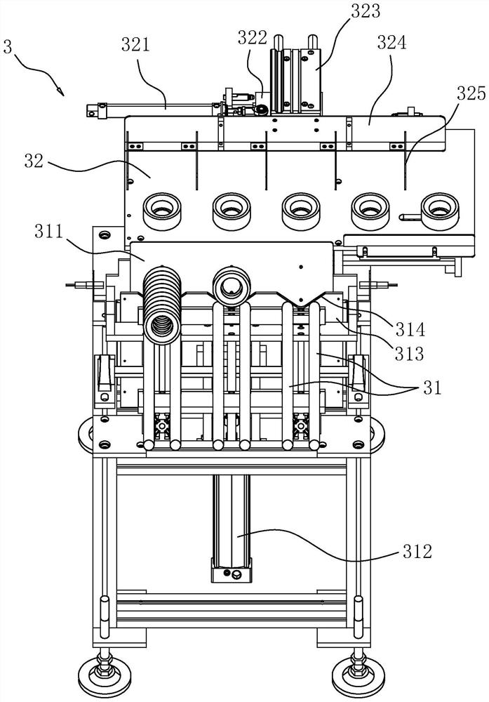
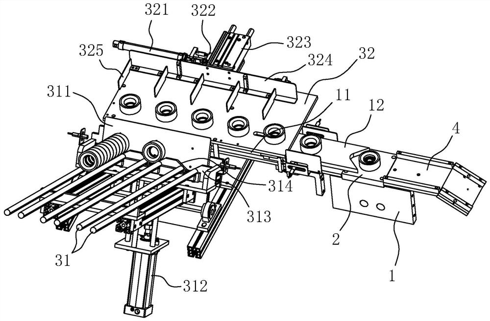
[0038] refer to figure 2 and image 3, feeding mechanism 3 comprises feeding rack 31, feeding table 32, and wherein...


PUM


Abstract

The invention relates to a workpiece conveying system and relates to the field of automatic equipment. The workpiece conveying system comprises a frame, a workbench, a discharging passage connected tothe workbench; an opening formed in the tail end of the discharging passage; a material blocking plate is arranged at the tail end of the discharging passage; a driving source and a rotating seat driven by the driving source to rotate are arranged on the frame; the rotating seat comprises a bottom plate and a side plate; the bottom plate is positioned in the opening; the top face of the bottom plate is connected with the top face of the discharging passage; a material placing frame is arranged on the side, deviating from the discharging passage, of the rotating seat; material placing rails are arranged on the material placing frame; the rotating seat can rotate to enable the bottom plate to rotate to the position of the side plate; and the side plate can rotate to a state that the plate face is inclined downwards. Workpieces passing through the workpiece conveying system can be automatically arranged in order in an end face abutting mode, so that storage, batch carrying and transportation of the workpieces are greatly facilitated. The material placing rails can be automatically switched, so that the material storage capacity of the material placing frame is improved, and meanwhile, workers can delay time to discharge the workpieces on the material placing rails; and by arranging a baffle and a pushing block I, the reliability of workpiece discharging is high.

Description

technical field [0001] The present application relates to the field of automation equipment, in particular to a workpiece conveying system. Background technique [0002] Before and after the equipment processes a large number of identical workpieces, if the two ends of the workpiece are parallel, and the height of the workpiece is smaller than its width and length, the workpiece is generally placed in such a way that the end faces are offset, so that the placement is neat and convenient. Storage, batch handling and transportation of workpieces. The same is true for cylindrical workpieces. [0003] In the automation system, if it is necessary to process the end face of the workpiece, the workpiece needs to be separated and processed separately on the end face. After the processing is completed, if the workpiece is to be restored to a neatly arranged state where the end faces abut, manual operations are required. There is the defect that the amount of manual labor is large. ...

Claims


Application Information

Patent Timeline
IPC IPC(8): B65G47/26B65G47/82
CPCB65G47/261B65G47/82
Inventor 王连方
Owner 温岭市微米自动化设备有限公司
Learn More