
Speed control method and system for hump humping vehicles

A speed control, hump slipping technology, applied in railway car body parts, mandatory railway stop, railway signal and safety, etc., can solve the problem of difficulty in receiving and shorten the time of occupying the reducer section, and reduce the occurrence of overspeed. The probability of , the effect of increasing the braking distance

Pending Publication Date: 2020-12-08
CRSC RESEARCH & DESIGN INSTITUTE GROUP CO LTD
View PDF4 Cites 1 Cited by
  • Summary
  • Abstract
  • Description
  • Claims
  • Application Information

AI Technical Summary

Problems solved by technology

[0004] The head-stop and tail-stop braking method first uses the high braking energy of the reducer and the high energy of the car group to calculate the head-release amount, and then uses the head-stop and tail-stop braking method to control the speed of the car group. The high value of the braking energy of the reducer is the average braking energy of the reducer provided by the reducer equipment manufacturer after many tests. The actual braking energy varies greatly, that is, the braking energy used in the calculation may not match the actual braking energy. If the difference between the two is large, the following two situations may occur:
[0005] If the actual braking energy of the reducer on the vehicle is much greater than the braking energy used in the calculation, the actual speed of the vehicle group has already reached the speed value required by the operation before the vehicle group leaves the reducer section, and it is difficult to stop. To achieve the best effect of shortening the time of occupying the reducer section;

Method used


Image

  • Speed control method and system for hump humping vehicles
  • Speed control method and system for hump humping vehicles
  • Speed control method and system for hump humping vehicles

Examples


Embodiment Construction

[0082] In order to make the purpose, technical solutions and advantages of the embodiments of the present invention more clear, the technical solutions in the embodiments of the present invention will be clearly and completely described below in conjunction with the accompanying drawings in the embodiments of the present invention. Obviously, the described embodiments It is a part of embodiments of the present invention, but not all embodiments. Based on the embodiments of the present invention, all other embodiments obtained by persons of ordinary skill in the art without making creative efforts belong to the protection scope of the present invention.

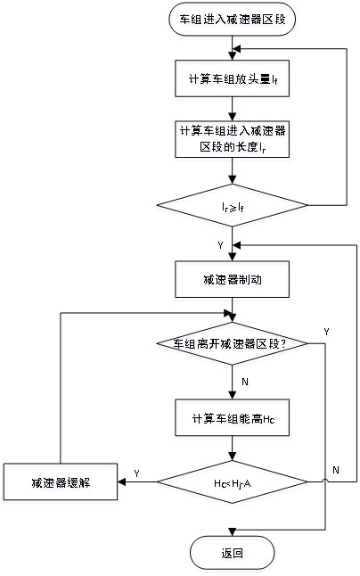
[0083] figure 1 It shows the flow chart of the speed control method of the humped vehicle in the embodiment of the present invention. Such as figure 1 As shown, detect whether the vehicle group enters the reducer section.

[0084] After the vehicle group enters the speed reducer section, dynamically calculate the head-setti...


PUM


Abstract

The invention provides a speed control method and system for hump humping vehicles. The speed control method comprises the steps that whether a vehicle set enters a speed reducer section or not is detected; after the vehicle set enters the speed reducer section, the head releasing amount lf of the vehicle set and the length lr of the portion, entering the speed reducer section, of the vehicle setare dynamically calculated, and the lf with the lr are compared; whether the speed reducer starts braking or not is judged according to a comparison result of lf and lr; and if the speed reducer starts braking, whether the vehicle set leaves the speed reducer section or not is detected. According to the speed control method and system, in the humping process of the vehicle set, the speed reducer is braked in advance, the braking distance is increased, the probability of overspeed can be effectively reduced for special vehicles, the energy height of the vehicle set is dynamically calculated andcompared with the braking energy height of the speed reducer to dynamically regulate and control the action of the speed reducer, the average speed of the vehicle set passing through the speed reducer section is effectively increased, and the hump operation efficiency is improved.

Description

technical field [0001] The invention belongs to the field of hump-running vehicles, in particular to a speed control method and system for hump-running vehicles. Background technique [0002] The hump of the railway marshalling yard is a small hill built on the ground in the shape of the back of a camel. It is designed with an appropriate slope and the railway is laid on it. The potential energy generated by the gravity of the vehicle and the slope of the hump is supplemented by locomotive thrust to disintegrate a part of the train. Shunting equipment. During the hump shunting operation, the shunting machine first pushes the train to the hump. When the front train group is close to the peak, the coupler is lifted. At this time, the vehicle's own gravity can be used to slide down the slope automatically. to the scheduled line of the marshalling yard, which can greatly improve the efficiency of shunting operations. During the sliding process of the vehicle group relying on i...

Claims


Application Information

Patent Timeline
Patent Type & Authority Applications(China)
IPC IPC(8): B61L23/00B61K7/16
CPCB61L23/00B61K7/16
Inventor 薛晓兵赵强钟卫红傅芸李东奎韩秋月张维华
Owner CRSC RESEARCH & DESIGN INSTITUTE GROUP CO LTD
Learn More