Endoscope tip and endoscope

An endoscope and tip technology, which is applied in the field of medical endoscopes, can solve the problems of small lighting output area, affecting assembly efficiency, collision of the light source of the tip cover, etc., so as to improve production efficiency and yield, improve lighting efficiency and life. , the effect of increasing the lighting output angle

Pending Publication Date: 2020-12-08
珠海万图医疗技术有限公司
View PDF1 Cites 4 Cited by
  • Summary
  • Abstract
  • Description
  • Claims
  • Application Information

AI Technical Summary

Problems solved by technology

The lens at the tip of the traditional endoscope is installed in the mount. During installation, the lens needs to be adjusted repeatedly to align the lens with the chip, so that the chip can achieve the best imaging effect. Using this assembly method has a low yield rate. , The disadvantage of low assembly efficiency
In addition, the lighting source of the tip of the traditional endoscope is single-point or two-point lighting, and its lighting output area is small. After a period of use, the illumination and illumination range will gradually attenuate, resulting in insufficient image illumination, which will affect user observation. and judgment
Existing patent CN208640661U discloses a mounting structure for the tip of an endoscope. This patent also discloses a mounting seat and a tip cover. Two positioning blocks are arranged on the outside of the mounting seat, and a light source is arranged on each positioning block. Provide a good lighting environment for the lens, but because the tip sleeve is set on the outside of the mount, when the tip sleeve is set, the tip sleeve is likely to collide with the light source, which not only affects the assembly efficiency, but also easily affects the stability of the light source position

Method used


Image

  • Endoscope tip and endoscope
  • Endoscope tip and endoscope
  • Endoscope tip and endoscope

Examples


Embodiment Construction

[0022] Endoscope tip embodiment

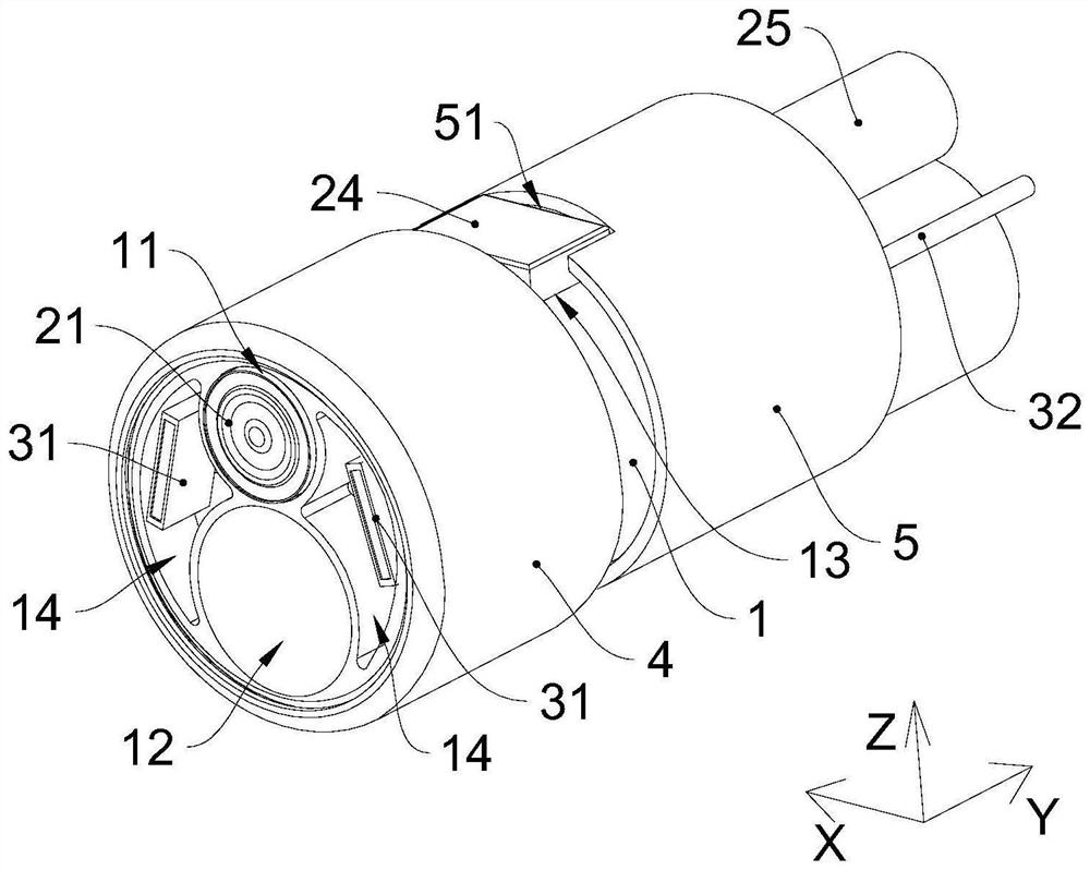
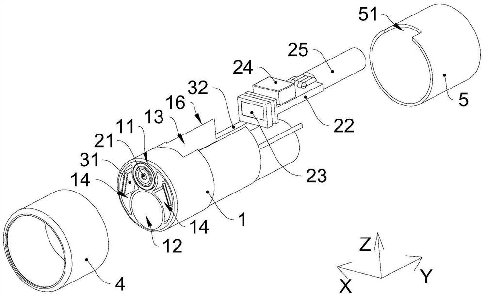
[0023] see figure 1 and figure 2 , The tip end of the endoscope includes a mounting base 1, a camera assembly, a lighting assembly, an insulating protective sleeve 4 and a snake joint sleeve 5. For the convenience of description, the axial direction of the tip of the endoscope is set as the Y direction, the first radial direction of the tip of the endoscope is set as the X direction, and the second direction perpendicular to the first radial direction of the tip of the endoscope is The radial direction is set to the Z direction. Both the camera assembly and the lighting assembly are arranged on the mounting base 1, and the insulating protective sleeve 4 and the snake bone connecting sleeve 5 are respectively sleeved on both ends of the mounting base 1 in the Y direction. The distance between the insulating protective sleeve 4 and the snake bone connecting sleeve 5 is preset. Set distance.

[0024] The camera assembly includes a lens 21 an...


PUM


Abstract

The invention provides an endoscope tip and an endoscope. The endoscope tip comprises a mounting base, and a camera assembly and an illumination assembly which are arranged on the mounting base; the mounting base is provided with a lens mounting hole, an instrument channel, a chip mounting groove and an illumination mounting groove; the lens mounting hole and the instrument channel are arranged along a Z direction; the lens mounting hole and the chip mounting groove are arranged in the Y direction and communicate with each other the lens mounting hole is aligned with the center of the chip mounting groove; the illumination mounting groove is formed in one side of the lens mounting hole, and the illumination assembly is arranged in the illumination mounting groove; the camera assembly comprises a lens and an image signal transmission unit; the lens is arranged in the lens mounting hole, the image signal transmission unit is arranged in the chip mounting groove, and the lens is connectedwith the image signal transmission unit; and the endoscope comprises an operating handle, an insertion tube and the endoscope tip, wherein the insertion tube is connected between the operating handleand the endoscope tip. The endoscope tip and the endoscope have the advantages of simple and convenient assembly and no need of repeatedly adjusting the position of the lens.

Description

technical field [0001] The invention relates to the fields of medical endoscopes and industrial endoscopes, in particular to an endoscope tip and the endoscope. Background technique [0002] An endoscope is an electronic instrument commonly used in medical inspection and industrial flaw detection. The endoscope includes an insertion part that extends into the human body or inside the equipment and an operating handle that controls the movement, camera and lighting of the insertion part. The insertion part includes an insertion tube. and a tip end, a camera and a light source are installed on the tip end. The lens at the tip of the traditional endoscope is installed in the mount. During installation, the lens needs to be adjusted repeatedly to align the lens with the chip, so that the chip can achieve the best imaging effect. Using this assembly method has a low yield rate. , The disadvantage of low assembly efficiency. In addition, the lighting source of the tip of the tra...

Claims


Application Information

Patent Timeline
IPC IPC(8): A61B1/05A61B1/06A61B1/07A61B1/018G02B23/24
CPCA61B1/00071A61B1/018A61B1/05A61B1/0676A61B1/0684A61B1/07G02B23/2423G02B23/2461G02B23/2484
Inventor 蒋卓韶
Owner 珠海万图医疗技术有限公司
Why Eureka
Try Eureka