
Method for operating a wastewater-lifting system

A waste water and equipment technology, applied in the direction of mechanical equipment, chemical instruments and methods, water supply devices, etc., can solve problems such as functional capacity problems, lack of cut-off mechanism, etc., and achieve the effect of easy cleaning and maintenance

Active Publication Date: 2020-12-04
KSB AG
View PDF11 Cites 0 Cited by
  • Summary
  • Abstract
  • Description
  • Claims
  • Application Information

AI Technical Summary

Problems solved by technology

[0006]Such a ball as a cut-off mechanism is disadvantageous in this respect because, for example, relatively small solid or clogging materials remain unchanged in the pre-cleaned waste water May cause problems during shutdown
In addition, clumping, calcification, etc. are often observed, which likewise make functional capacity problematic
As long as work is also carried out within the framework of EP 1 108 822 B1 with the bypass there in the form of a discharge line parallel to the connection line, the shut-off mechanism is already missing

Method used


Image

  • Method for operating a wastewater-lifting system
  • Method for operating a wastewater-lifting system
  • Method for operating a wastewater-lifting system

Examples


Embodiment Construction

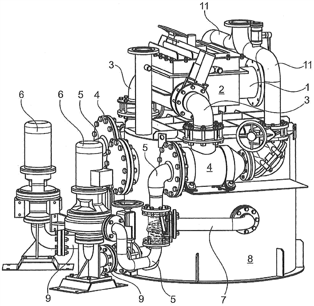
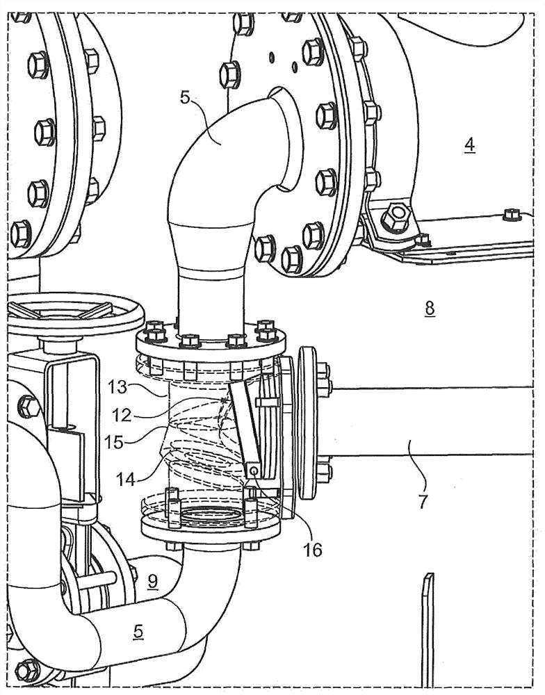
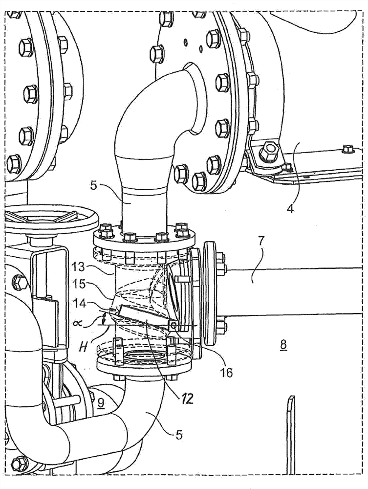
[0029] A waste water lifting device is shown in the drawing. The waste water lifting device firstly has an inflow 1 for waste water, which in the present exemplary embodiment diverts the waste water via an inflow distributor 2 and a feed line 3 into two clogging material collection containers 4 . Within the scope of the present exemplary embodiment, the waste water lifting device is designed as a symmetrical pair and has two clogging material collection containers 4 and additionally has two discharge lines or connecting lines 5 through which Alternatively, the lines are connected such that waste water pre-cleaned by means of the clogging material collection container 4 accordingly enters the associated pump 6 .

[0030] One clogging material collection container 4 or two clogging material collection containers 4 each serve to bring about the result that clogging material or solid material remaining in the associated clogging material collection container 4 is generally passed ...


PUM


Abstract

The invention relates to a method for operating a wastewater-lifting system, in which wastewater loaded with bulky materials is guided through a bulky material collection tank (4) having at least oneseparating screen arranged in its interior, in which furthermore, during the intake of wastewater, the bulky materials are retained in the bulky material collection tank (4), and precleaned wastewateris fed to a pump (6) via a connection line (5), and in which the precleaned wastewater passes into the liquid collection tank (8) via the pump (6) and via a bypass line (7) connected to the connection line (5). According to the invention, a pivoting flap (12) is additionally provided in the connection line (5), said flap, during the intake of wastewater, closing the connection line (5) apart froma flushing cross section (14) and opening the bypass line (7) and, during the pumping operation, opening the connection line (5) and closing the bypass line (7).

Description

technical field [0001] The invention relates to a method for operating a waste water lifting plant, according to which waste water loaded with clogging material is passed through a clogging material collection container having at least one separating screen arranged inside it, according to which method additionally in the waste water The inflow causes the clogging material to be trapped in the clogging material collection container and the pre-cleaned waste water is conveyed via the connecting line to the pump and finally to the liquid collection container, and according to the method the pre-cleaned waste water is on the one hand Into the liquid collection container via a pump and, on the other hand, via a bypass line connected to the connecting line. Background technique [0002] Waste water lifting plants are often used to lift incoming waste water to a specific level, for example for further treatment in waste water purification plants. Because the waste water is loaded...

Claims


Application Information

Patent Timeline
Patent Type & Authority Applications(China)
IPC IPC(8): E03F5/22E03F5/14E03C1/122
CPCE03C1/1227E03F5/14E03F5/22E03F5/10F04D15/029
Inventor M·贝克J·盖尼茨T·彭斯勒
Owner KSB AG
Learn More