Eureka AIR delivers breakthrough ideas for toughest innovation challenges, trusted by R&D personnel around the world.

Film sticking machine

A film lamination machine and frame technology, which is applied in the direction of electrical components, printed circuit manufacturing, printed circuits, etc., can solve the problems of low production efficiency and dependence on manual participation, and achieve the effect of saving labor costs and improving processing production efficiency

Pending Publication Date: 2020-12-04
深圳市火焱激光设备有限公司
View PDF0 Cites 1 Cited by
  • Summary
  • Abstract
  • Description
  • Claims
  • Application Information

AI Technical Summary

Problems solved by technology

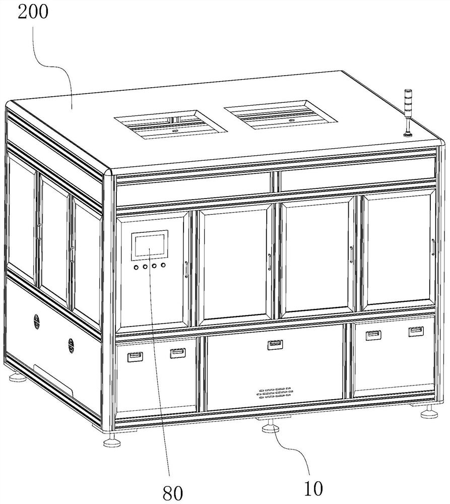
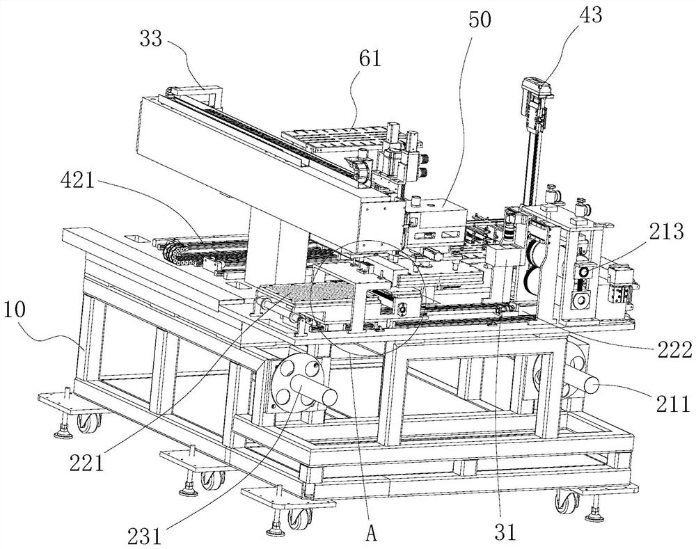
[0003] The purpose of the present invention is to provide a film laminating machine, which aims to solve the problems of relying on manual participation and low production efficiency in the process of mounting copper foil film materials on circuit boards in the prior art

Method used


Image

  • Film sticking machine
  • Film sticking machine
  • Film sticking machine

Examples


Embodiment Construction

[0024] Embodiments of the present invention are described in detail below, examples of which are shown in the drawings, wherein the same or similar reference numerals designate the same or similar elements or elements having the same or similar functions throughout. The embodiments described below by referring to the figures are exemplary and are intended to explain the present invention and should not be construed as limiting the present invention.

[0025] In describing the present invention, it should be understood that the terms "length", "width", "upper", "lower", "front", "rear", "left", "right", "vertical", The orientation or positional relationship indicated by "horizontal", "top", "bottom", "inner", "outer", etc. are based on the orientation or positional relationship shown in the drawings, and are only for the convenience of describing the present invention and simplifying the description, rather than Nothing indicating or implying that a referenced device or element...


PUM


Abstract

The invention belongs to the technical field of circuit board production equipment, and particularly relates to a film sticking machine. The film sticking machine comprises a rack, a material roll output mechanism, a first feeding mechanism, a roll paper winding mechanism, a second feeding mechanism, a film sticking mechanism and a discharging base, wherein a material roll is discharged and conveyed to a containing base through the material roll output mechanism, the first feeding mechanism and the roll paper winding mechanism; a circuit board is placed in a circuit board storage base and conveyed to a middle platform through a conveying structure; then a copper foil film material is adsorbed through the film sticking mechanism and conveyed to the middle platform for to film sticking operation; a product is obtained after film sticking operation is completed, and finally, the product is conveyed to the discharging base for storage through the conveying structure; and the whole machining process of feeding, film sticking and product discharging is cyclically repeated in the same manner to realize continuous processing and production. By applying the technical scheme, the problems ofdependence on manual participation and low production efficiency in the process of mounting copper foil film materials on circuit boards in the prior art are solved.

Description

technical field [0001] The invention belongs to the technical field of circuit board production equipment, and in particular relates to a film sticking machine. Background technique [0002] In the circuit board production process, copper foil film material needs to be mounted on the circuit board. In the existing technology, the process of mounting copper foil film materials on circuit boards, whether it is loading, mounting, or unloading, is still in a semi-automatic production state, and the processing operations at each processing position cannot lack manual participation , not only increases the labor intensity of workers, but also increases the labor cost of enterprise production and reduces production efficiency. Contents of the invention [0003] The object of the present invention is to provide a film laminating machine, aiming at solving the problems of relying on manual participation and low production efficiency in the process of mounting copper foil film mate...

Claims


Application Information

Patent Timeline
Patent Type & Authority Applications(China)
IPC IPC(8): H05K3/00
CPCH05K3/00
Inventor 吴杰阳政
Owner 深圳市火焱激光设备有限公司
Why Eureka
Eureka Blog
Learn More