Conducting bar, junction box for high-voltage doubly-fed wind generator and installation method of junction box

A technology for wind turbines and junction boxes, which is used in the manufacture of motor generators, electromechanical devices, circuits, etc., can solve the problems of large space and bulkiness of the junction box, and achieve the effect of compact design and small space occupation.

Pending Publication Date: 2020-12-04
CRRC XIAN YONGE JIELI WIND ENERGY CO LTD
View PDF12 Cites 0 Cited by
  • Summary
  • Abstract
  • Description
  • Claims
  • Application Information

AI Technical Summary

Problems solved by technology

[0004] The purpose of the present invention is to overcome the above-mentioned shortcomings of the prior art, and provide a conductive bar, a junction box for a high-voltage double-fed wind generator and an installation method thereof, so as to solve the problem that the junction box for a high-voltage double-fed wind generator takes up a large space and is heavy

Method used


Image

  • Conducting bar, junction box for high-voltage doubly-fed wind generator and installation method of junction box
  • Conducting bar, junction box for high-voltage doubly-fed wind generator and installation method of junction box
  • Conducting bar, junction box for high-voltage doubly-fed wind generator and installation method of junction box

Examples


Embodiment 1

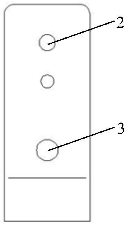
[0043] First, see figure 1 As shown, the present invention provides a conductive bar, which is applied in a junction box of a high-voltage doubly-fed wind turbine. The conductive bar 11 includes a conductive bar body, and the conductive bar body includes first, second and third mounting holes. And the connection lines at the positions of the three installation holes form a triangle; the first installation hole 2 is used to connect with the high-voltage insulator 5 in the junction box; the second installation hole 3 is used to connect with the stator lead wire 6 of the generator, and the stator leads The wire 6 is connected to the stator coil through the body of the junction box; the third installation hole 4 is used to connect with the user cable 7, and the user cable 7 is connected to the power grid through the body of the junction box.

[0044] Further, the connection lines of the positions of the three installation holes form an isosceles triangle, and the apex corners of t...

Embodiment 2

[0065] In the first aspect, this embodiment provides a conductive bar, the conductive bar 11 includes a conductive bar body, and the conductive bar body includes a first, a second and a third mounting hole, and the connection lines at the positions of the three mounting holes are formed. Triangle; the first installation hole 2 is used to connect with the high-voltage insulator 5 in the junction box; the second installation hole 3 is used to connect with the stator lead wire 6 of the generator, and the stator lead wire 6 is connected to the stator coil through the junction box body; The third installation hole 4 is used to connect with the user cable 7, and the user cable 7 is connected to the power grid through the junction box body.

[0066] see Figure 2-3 As shown in the figure, the connecting lines of the positions of the three mounting holes form a right-angled triangle, and the right angles are rounded; wherein, the first mounting hole 2 and the second mounting hole 3 ar...


PUM


Abstract

The invention belongs to the technical field of high-voltage doubly-fed wind generators, and relates to a conducting bar, a junction box for a high-voltage doubly-fed wind generator and an installation method of the junction box. The conducting bar simultaneously meets the assembly requirements of a motor side and a user cable. According to the junction box, three-phase conducting bars are respectively positioned on an insulating column bracket according to the position layout of the three-phase conducting bars, a distance between every two adjacent conducting bars is more than or equal to 220mm, and every two conducting bars are arranged to be compact and are small in occupied space. When the junction box is installed, a stator leading-out wire freely overhangs in a stator junction box,so on one hand, the bending radius of the stator leading-out wire is ensured, and the use reliability of the cable can be improved; and on the other hand, the insulation resistance of the surface of the cable can be increased by lengthening the effective length of the cable, thereby enhancing the insulation performance of the cable.

Description

technical field [0001] The invention belongs to the technical field of high-voltage doubly-fed wind power generators, and relates to a junction box for generators, in particular to a conductive row, a junction box for high-voltage doubly-fed wind power generators and an installation method thereof. Background technique [0002] At present, the country is vigorously developing new energy utilization technology, thereby promoting the continuous innovation and progress of wind power generation technology and wind turbine design and manufacturing technology. The voltage level of the high-voltage power supply network in various parts of my country is mainly 10kV. If a 10.5kV high-voltage doubly-fed generator is installed, one less step-up transformer can be installed. The capacity of the step-up transformer is the same as the power of the wind turbine, which is not only expensive, but also The control is complicated, which reduces the reliability of the whole wind turbine. [000...

Claims


Application Information

Patent Timeline
IPC IPC(8): H02K5/22H02K3/50H02K15/00H01R25/16
CPCH02K5/225H02K3/50H02K3/505H02K15/00H02K15/0062H01R25/16
Inventor 牛海龙池佃旭李新奇刘军婷霍永强符致昭张广兴
Owner CRRC XIAN YONGE JIELI WIND ENERGY CO LTD
Why Eureka
Try Eureka