Power distribution cabinet with rapid maintenance function

A power distribution cabinet and functional technology, applied in substation/power distribution device housing, electrical components, substation/switch layout details, etc., can solve problems such as unfavorable maintenance components, maintenance misoperation, and inability to perform targeted maintenance. To achieve a highly targeted maintenance effect

Inactive Publication Date: 2020-12-04
合肥源康信息科技有限公司
View PDF1 Cites 6 Cited by
  • Summary
  • Abstract
  • Description
  • Claims
  • Application Information

AI Technical Summary

Problems solved by technology

[0006] The purpose of the present invention is to provide a power distribution cabinet with a quick maintenance function to solve the problem that the existing electric control cabinet in the above background technology mostly pushes out all the installation boards on which the electricity is installed and cannot carry out targeted maintenance. Maintenance, it is easy to cause misoperation in maintenance, and all installation boards occupy a large area, which is not conducive to the maintenance of components close to the inside of the power distribution cabinet
[0008] When working, because most of the existing electric control cabinets push out all the installation boards for installing electrical installations during maintenance, they cannot be repaired in a targeted manner, which will easily lead to misoperation in maintenance. It is beneficial to repair the components close to the inside of the power distribution cabinet. By turning off the power of the control cabinet, determine the damaged components, start the driving mechanism to drive the U-shaped plate to slide up and down in the control cabinet body, and adjust the U-shaped plate to the rectangle of the component that needs to be repaired. At the middle position of the installation plate, push the two second racks to slide in the first rectangular chute, drive the two second gears to rotate, and the two second gears rotate at the same time to drive the two third racks and the rectangular long bar in the The fixed slide rail moves to the front side. When the third rack moves to the front side, it drives the first push plate to move together. The first push plate pushes and slides the long bar and the boss-shaped guide block. The boss-shaped guide block acts as the second One guide rod, press the first guide rod to the two, the first guide rod drives the rectangular positioning block to withdraw from the positioning groove through the first sliding rod, the first push plate continues to move forward, pushes the rectangular mounting plate, and the rectangular mounting plate is installed The plate slides forward in the first T-shaped chute in the fixed block, and the boss-shaped guide block moves forward. The first spring makes the rectangular positioning block slowly return to the initial position. When the rectangular mounting plate moves forward, the functions of both sides The position falls from the lifting groove. When falling, it drives the ladder rod to slide down together. The first gear at the front end of the ladder rod meshes with the first rack and rotates. The damping sleeve acts on the ladder rod to slow down the rotation of the ladder rod, making the rectangular mounting plate slow down. slide down to the top of the two maintenance positioning plates in the lifting groove, and then repair the components that need to be repaired. Return to the initial position. When the rectangular mounting plate slides in the first T-shape, the third rack is pulled back to the initial position. The third rack drives the second rack to return to the initial position through the second gear. The first push plate The second T-shaped chute drives the sliding strip back to the initial position, and the rectangular mounting plate opens the rectangular positioning block through the installation guide groove at the rear end and inserts it into the positioning groove to reposition the rectangular mounting plate to complete the maintenance, so as to achieve When the electric control cabinet is being repaired, it is only necessary to push out the mounting boards of the installation components that need to be repaired, and carry out targeted maintenance, which is not easy to cause misoperation in the maintenance. Pushing out all the mounting boards occupies a small area, which is convenient for maintenance close to the power distribution Components inside the cabinet

Method used


Image

  • Power distribution cabinet with rapid maintenance function
  • Power distribution cabinet with rapid maintenance function
  • Power distribution cabinet with rapid maintenance function

Examples


Embodiment Construction

[0030] The following will clearly and completely describe the technical solutions in the embodiments of the present invention with reference to the accompanying drawings in the embodiments of the present invention. Obviously, the described embodiments are only some, not all, embodiments of the present invention. Based on the embodiments of the present invention, all other embodiments obtained by persons of ordinary skill in the art without creative efforts fall within the protection scope of the present invention.

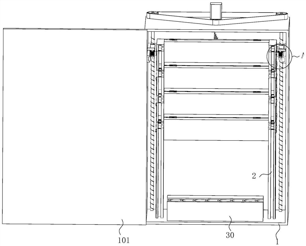
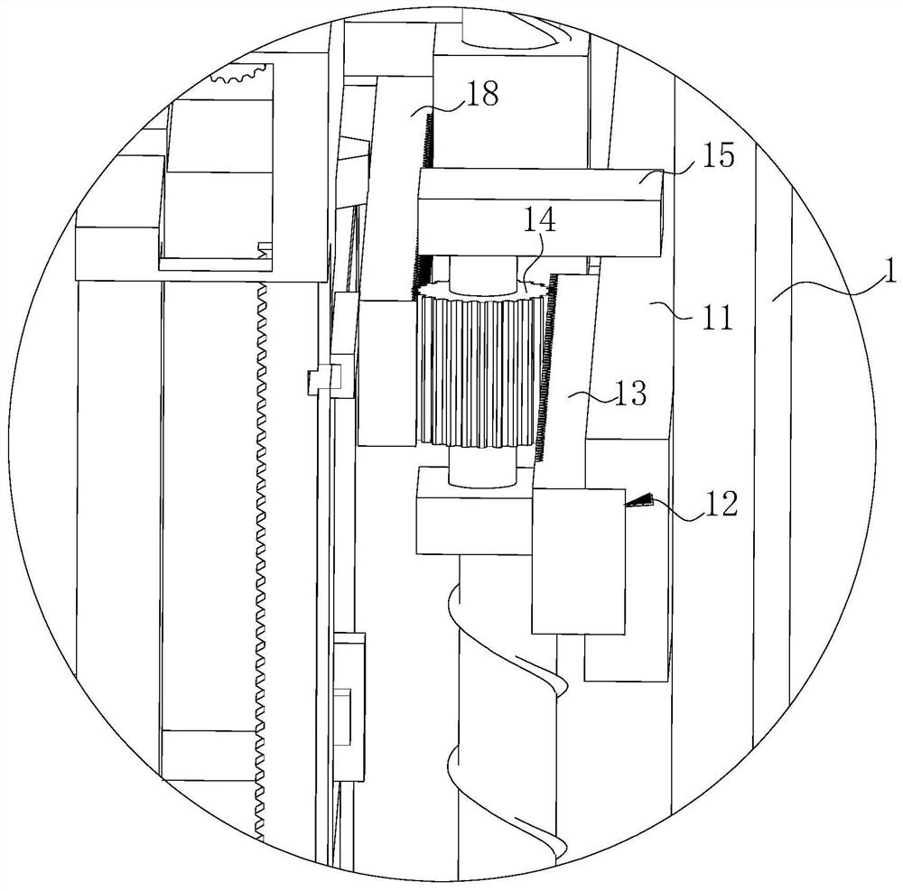
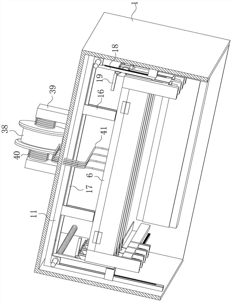
[0031] see Figure 1-10 , the present invention provides a technical solution: a power distribution cabinet with a quick maintenance function, including a control cabinet body 1, the front of the control cabinet body 1 is hinged with a box door 101, and the control cabinet body 1 is fixedly connected with two A mounting frame 2, the upper ends of the two mounting frames 2 are fixedly connected with a number of fixed blocks 3 equidistantly distributed, the mounting ...


PUM


Abstract

The invention discloses a power distribution cabinet with a rapid maintenance function in the technical field of power distribution cabinets. The power distribution cabinet comprises a control cabinetbody, wherein two installation frames are fixedly connected to the interior of the control cabinet body, the upper ends of the two installation frames fixedly communicate with a plurality of fixed blocks which are distributed at equal intervals, a lifting groove is jointly formed in the installation frames and the fixed blocks, and the two fixing blocks on the same horizontal line on the left side and the right side are jointly connected with a rectangular mounting plate in a sliding mode through a first T-shaped sliding groove. According to the power distribution cabinet, a U-shaped plate isdriven by a driving mechanism to ascend and descend to a proper position so as to unfold the rectangular mounting plate needing to be positioned and then retreats and descends to a maintenance position, thus when an electric control cabinet is maintained, only the mounting plates of the mounting component needing to be maintained needs to be pushed out, targeted maintenance is carried out, the misoperation phenomenon during maintenance is not likely to occur, the maintenance efficiency is improved, and all the mounting plates are pushed out to occupy a small area, thereby facilitating the maintenance of components close to the inner side of the power distribution cabinet.

Description

technical field [0001] The invention relates to the field of power distribution cabinets, in particular to a power distribution cabinet with a quick maintenance function. Background technique [0002] The electric control cabinet is a common power supply control equipment. Its main purpose is to assemble switchgear, measuring instruments, protective appliances and auxiliary equipment in a closed metal cabinet according to the requirements of electrical wiring, so as to meet the requirements of normal operation of the power system without endangering people and surroundings. Equipment Security. [0003] Invention patent CN201910704805.7 A power distribution cabinet that is easy to maintain, including a bottom plate, one side of the bottom plate is provided with a vertical plate, and the top of the vertical plate is provided with a connecting plate extending to the other side of the bottom plate. The connecting plate is provided with a mounting plate parallel to the vertical ...

Claims


Application Information

Patent Timeline
Patent Type & Authority Applications(China)
IPC IPC(8): H02B1/30H02B1/32H02B1/36H02B1/38H02B1/04B65H75/44
CPCB65H75/44H02B1/04H02B1/30H02B1/306H02B1/32H02B1/36H02B1/38
Inventor 杨琪陆洋
Owner 合肥源康信息科技有限公司
Why Eureka
Try Eureka