FC optical fiber distribution frame dust cap picking device
A technology of optical fiber distribution frame and dust cap, which is applied in the field of dust cap extractor of FC optical fiber distribution frame, can solve the problems of affecting work efficiency, mistakenly touching pigtails, business interruption, etc., so as to improve work efficiency and ensure safety effect
- Summary
- Abstract
- Description
- Claims
- Application Information
AI Technical Summary
Problems solved by technology
Method used
Image
Examples
Embodiment 1
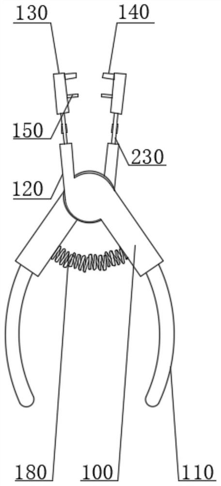
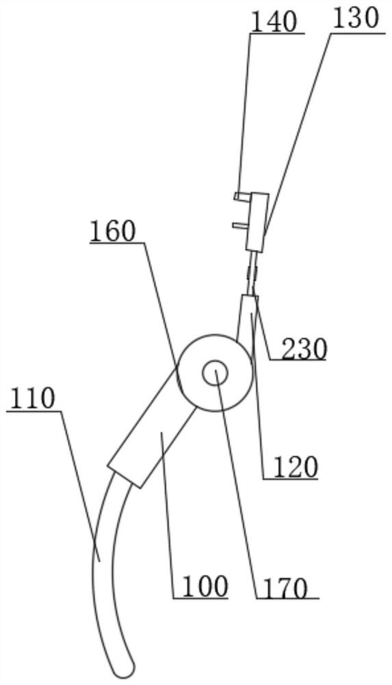
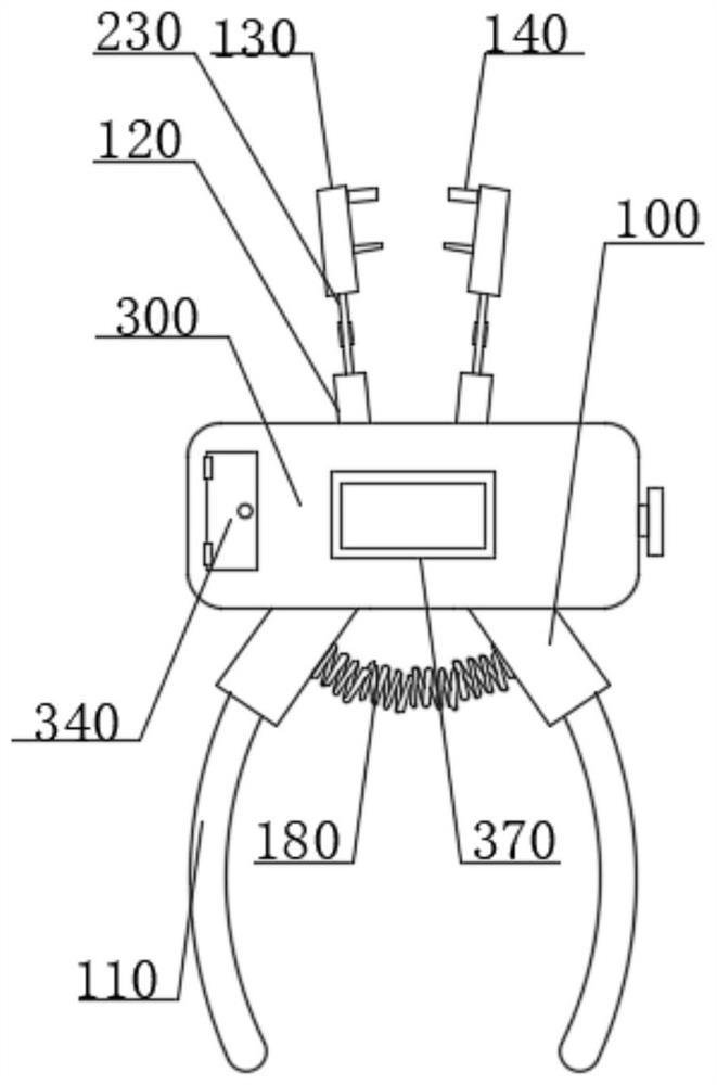
[0033] see Figure 1-10 , FC optical fiber distribution frame dust cap extractor, FC optical fiber distribution frame dust cap extractor, including claws 100; a first adjustment mechanism; an elastic reset mechanism; a second adjustment mechanism; and a detection mechanism; Two claws 100 are provided, one of the claws 100 is provided with a groove 160, and the two claws 100 are rotated and installed by the first rotating shaft 170; both of the claws 100 are adjusted by the second The mechanism is equipped with a first connecting rod 120 and a second connecting rod 130; the first adjusting mechanism is connected to the claw 100, and the first adjusting mechanism includes a housing 300, a first ratchet 400, a second ratchet 500 and a pull rod 800, the inner bottom end and the top end of the housing 300 are respectively provided with a first ratchet 400 and a second ratchet 500, and the first ratchet 400 and the second ratchet 500 are respectively rotatably connected to the housi...
Embodiment 2
[0050] As a preferred solution of Embodiment 1, please refer to Figure 12 and Figure 13 , the second adjustment mechanism includes a guide rod 230 and a threaded rod 200, two guide holes 220 are symmetrically opened on the first connecting rod 120 and the second connecting rod 130, and the axis of the second connecting rod 130 A threaded hole 210 is provided on the line, and a guide rod 230 is arranged in the guide hole 220 on the first connecting rod 120 and the second connecting rod 130, and one end of the threaded rod 200 is threadedly connected to the threaded hole 210. , and the other end of the threaded rod 200 is rotatably connected to the second connecting rod 130; the outer end of the threaded rod 200 is also fixedly connected with a handle 240;
[0051] Wherein, the guide rod 230 plays a role of guiding and limiting the first connecting rod 120 and the second connecting rod 130;
[0052] Wherein, the threaded holes 210 on the first connecting rod 120 and the seco...
Embodiment 3
[0055] As a preferred solution of Embodiment 1 or Embodiment 2, please refer to image 3 , Figure 4 and Figure 11 , the detection mechanism includes a battery 320, a controller 310, and a pressure sensor 330, the two second connecting rods 130 are fixedly connected with grab blocks 140, and the grab blocks 140 are fixedly connected with a pressure sensor 330 , and the pressure sensor 330 is electrically connected to the controller 310, the controller 310 is fixedly connected in the casing 300, and the battery 320 is fixedly installed in the casing 300, and the outer end of the casing 300 A display screen 370 is also fixedly connected, and the display screen 370 is electrically connected to the controller 310;
[0056] Wherein, the pressure sensor 330 is used to detect the clamping strength of the dustproof cap;
[0057] Wherein, the display screen 370 is used to display the clamping strength;
[0058] The two second connecting rods 130 are also fixedly connected with baf...
PUM
 Abstract
Description
Claims
Application Information
 - Generate Ideas
- Intellectual Property
- Life Sciences
- Materials
- Tech Scout
- Unparalleled Data Quality
- Higher Quality Content
- 60% Fewer Hallucinations
Browse by: Latest US Patents, China's latest patents, Technical Efficacy Thesaurus, Application Domain, Technology Topic, Popular Technical Reports.
© 2025 PatSnap. All rights reserved.Legal|Privacy policy|Modern Slavery Act Transparency Statement|Sitemap|About US| Contact US: help@patsnap.com


