
Arc aperture radar imaging method based on antenna phase pattern compensation and radar

A technology of aperture radar and imaging method, which is applied in the reflection/re-radiation of radio waves, radio wave measurement systems, and the use of re-radiation, etc. The effect of improving the imaging quality of the system and increasing the imaging accumulation angle

Pending Publication Date: 2020-12-04
宋千 +1
View PDF1 Cites 6 Cited by
  • Summary
  • Abstract
  • Description
  • Claims
  • Application Information

AI Technical Summary

Problems solved by technology

[0007] In view of the above-mentioned deficiencies in the prior art, the object of the present invention is to provide a circular aperture radar imaging method and radar based on antenna phase pattern compensation, which can solve the problem that the circular arc synthetic aperture radar azimuth resolution is limited by the antenna direction under the condition of large accumulation angle. The problem of falling due to the influence of graph inconsistency

Method used

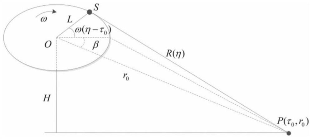
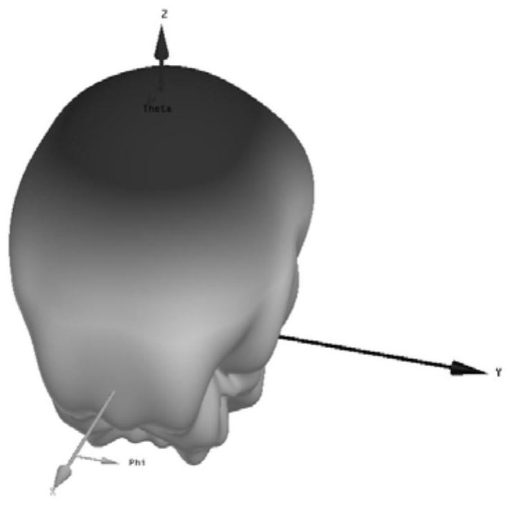

Image

  • Arc aperture radar imaging method based on antenna phase pattern compensation and radar
  • Arc aperture radar imaging method based on antenna phase pattern compensation and radar
  • Arc aperture radar imaging method based on antenna phase pattern compensation and radar

Examples


Embodiment Construction

[0062] In order to make the object, technical solution and effect of the present invention more clear and definite, the present invention will be further described in detail below with reference to the accompanying drawings and examples. It should be understood that the specific embodiments described here are only used to explain the present invention, not to limit the present invention.

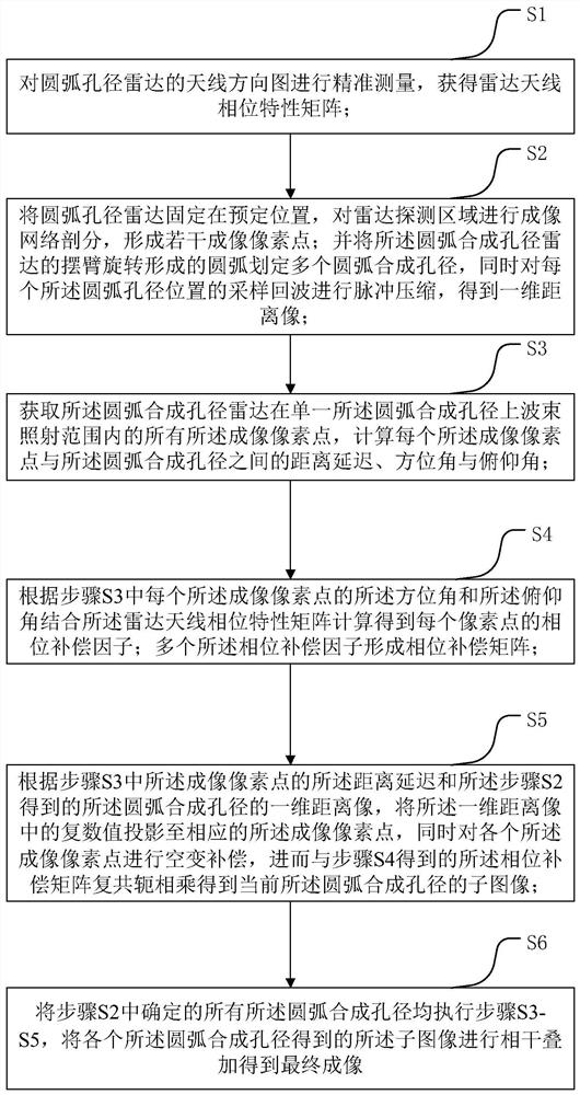
[0063] Please also refer to Figure 1-Figure 9 , the present invention provides a kind of arc aperture radar imaging method based on antenna phase pattern compensation, comprising steps:

[0064] S1. Accurately measure the antenna pattern of the arc aperture radar to obtain the phase characteristic matrix of the radar antenna;

[0065] S2. Fix the arc-arc aperture radar at a predetermined position, divide the radar detection area into an imaging network, and form a number of imaging pixels; and delineate a plurality of circles in the arc formed by the swing arm rotation of the arc-arc synth...


PUM


Abstract

The invention relates to an arc aperture radar imaging method based on antenna phase pattern compensation and a radar. The invention discloses an arc aperture radar imaging method based on antenna phase pattern compensation. The method comprises the following steps: S1, obtaining a radar antenna phase characteristic matrix; S2, fixing an arc aperture radar at a preset position, and performing imaging network subdivision on a radar detection area; S3, calculating a distance delay, an azimuth angle and a pitch angle of each imaging pixel point; S4, calculating to obtain a phase compensation factor of each pixel point; S5, performing space-variant compensation on each imaging pixel point at the same time, and further obtaining a sub-image of the current arc synthetic aperture according to thephase compensation matrix; and S6, coherently superposing the sub-images obtained by the arc synthetic apertures to obtain a final image. Phase inconsistency compensation is performed on each formedimaging pixel point so that Arc-SAR detection is enabled to break through the limitation of the 3dB beam angle of the antenna and the Arc-SAR imaging accumulation angle can be increased.

Description

technical field [0001] The invention relates to the field of radar imaging, in particular to an arc aperture radar imaging method and radar based on antenna phase pattern compensation. Background technique [0002] Synthetic Aperture Radar (SAR) is an all-time, all-weather, high-resolution imaging radar, which is widely used in the field of remote sensing. Since the SAR image has phase information, the non-contact and high-precision extraction of the deformation information of the imaging area can be realized through the interference processing of the SAR image sequence. In view of the above advantages of the SAR system, it has become one of the important means of ground deformation monitoring. However, traditional SAR systems are mostly carried on platforms such as satellites and aircraft, which makes the radar revisit time very long and cannot continuously monitor specific targets. Ground Based SAR (Ground Based SAR, GBSAR) is a miniaturized, low-cost SAR system that can...

Claims


Application Information

Patent Timeline
Patent Type & Authority Applications(China)
IPC IPC(8): G01S13/90G01S7/41
CPCG01S13/9056G01S7/41
Inventor 宋千王鹏宇
Owner 宋千
Learn More