
Solar LED garden flower lamp

A solar type, garden technology, applied in directions with built-in power supply, lighting auxiliary devices, lighting and heating equipment, etc., can solve problems such as monotony, affecting garden landscape effect, and eye-catching solar panels, so as to expand the area of ​​absorbing solar energy and improve lighting. Display effect, simple structure effect

Active Publication Date: 2020-12-04
WUHU SHENLONG NEW ENERGY TECH
View PDF4 Cites 0 Cited by
  • Summary
  • Abstract
  • Description
  • Claims
  • Application Information

AI Technical Summary

Problems solved by technology

[0003] Traditional courtyard lanterns need additional power connection, which is not energy-saving enough, and the lighting process is relatively monotonous, and cannot be dynamically illuminated, making the lighting effect poor
Although solar garden lanterns can save energy, the larger solar panels are more eye-catching during actual use, which affects the actual landscape effect of the garden

Method used


Image

  • Solar LED garden flower lamp
  • Solar LED garden flower lamp
  • Solar LED garden flower lamp

Examples


Embodiment 1

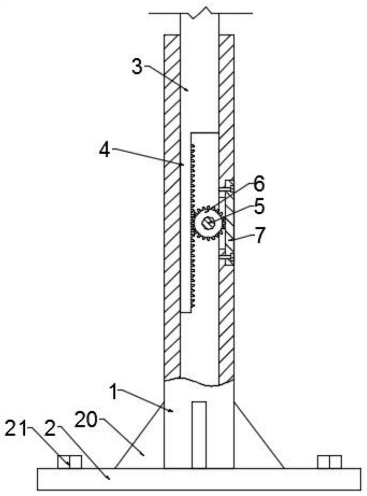
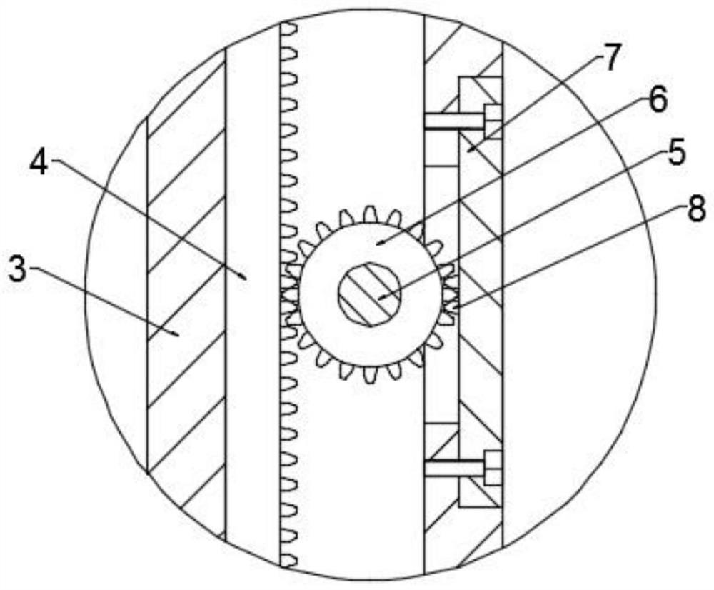
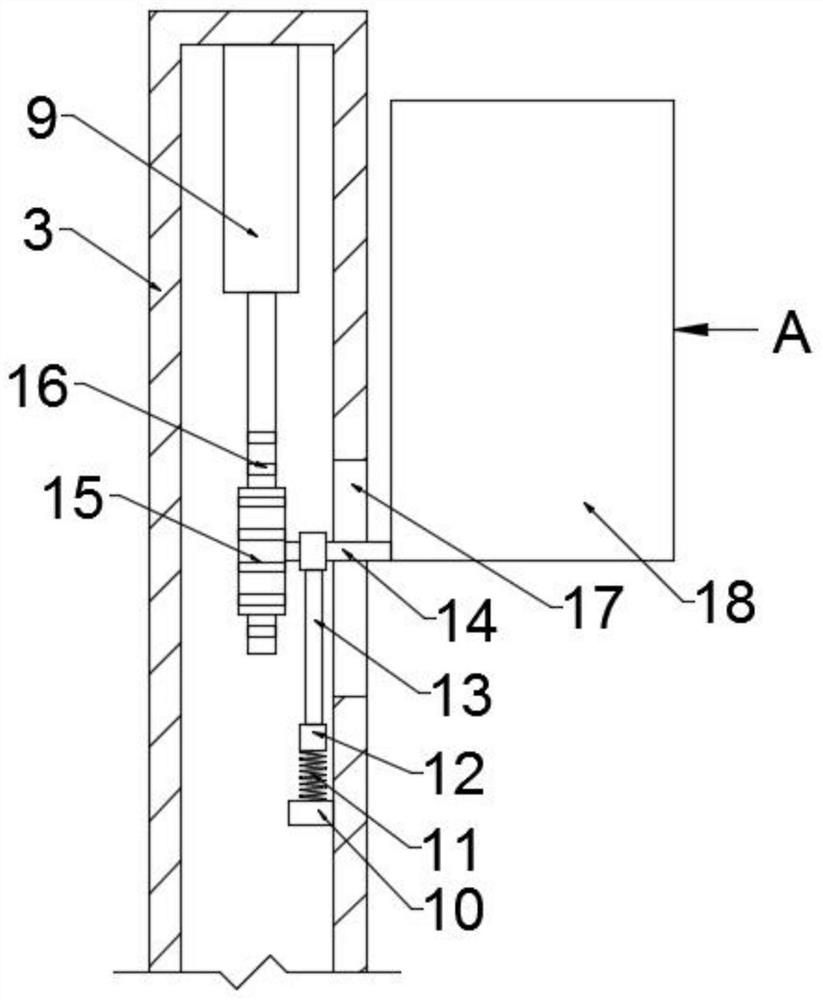
[0024] Example 1: Please refer to Figure 1-5 , a solar-powered LED garden lantern, including a lower sleeve 1 and a bottom plate 2, the lower sleeve 1 is fixed on the upper middle of the bottom plate 2, the inner side of the lower sleeve 1 is slidingly connected with a sleeve 3, and the left side of the bottom of the sleeve 3 is fixed A rack 4 is connected, the inner side of the lower sleeve 1 is fixedly connected with a first gear shaft 5, and the outer side of the first gear shaft 5 is rotatably connected with a limit rotation gear 6, and the limit rotation gear 6 meshes with the rack 4, and the lower sleeve The right side of the barrel 1 is fixedly connected with a side plate 7 by bolts, and the inner side of the side plate 7 is fixedly connected with a limit tooth 8, and the limit tooth 8 cooperates with the limit rotation gear 6;

[0025] When the present invention is in use, the lower sleeve 1 is fixed on the ground through the bottom plate 2. After fixing, the upper an...

Embodiment 2

[0036] Example 2: Please refer to Figure 1-5 , a solar-powered LED garden lantern, including a lower sleeve 1 and a bottom plate 2, the lower sleeve 1 is fixed on the upper middle of the bottom plate 2, the inner side of the lower sleeve 1 is slidingly connected with a sleeve 3, and the left side of the bottom of the sleeve 3 is fixed A rack 4 is connected, the inner side of the lower sleeve 1 is fixedly connected with a first gear shaft 5, and the outer side of the first gear shaft 5 is rotatably connected with a limit rotation gear 6, and the limit rotation gear 6 meshes with the rack 4, and the lower sleeve The right side of the barrel 1 is fixedly connected with a side plate 7 by bolts, and the inner side of the side plate 7 is fixedly connected with a limit tooth 8, and the limit tooth 8 cooperates with the limit rotation gear 6;

[0037] When the present invention is in use, the lower sleeve 1 is fixed on the ground through the bottom plate 2. After fixing, the upper an...


PUM


Abstract

The invention relates to a solar LED garden flower lamp, which relates to the flower lamp, and comprises a lower sleeve and a bottom plate, the lower sleeve is fixed to the middle of the upper portionof the bottom plate, a sleeve pipe is slidably connected to the inner side of the lower sleeve, a rack is fixedly connected to the left side of the bottom of the sleeve pipe, and a first gear shaft is fixedly connected to the inner side of the lower sleeve; the outer side of the first gear shaft is rotationally connected with a limiting rotating gear, the limiting rotating gear is meshed with therack, the right side of the lower sleeve is fixedly connected with a side plate through a bolt, and limiting teeth are fixedly connected to the inner side of the side plate and matched with the limiting rotating gear. The overall height of the lamp is limited and adjusted through the limiting rotating gear, meanwhile, the states of a rotating lamp box and a solar panel can be adjusted through stretching and retracting of an electric telescopic rod, the solar panel enlarges a solar energy absorption area when the lamp is opened, the rotating lamp box is rotated for illumination when the product is closed, meanwhile vertical movement of the rotating lamp box can be achieved, and the illumination display effect of the rotating lamp box is improved through movable illumination.

Description

technical field [0001] The invention relates to a lantern, in particular to a solar-powered LED garden lantern. Background technique [0002] At present, for the convenience of people's activities at night in the courtyard, it is a common phenomenon to set garden lanterns, that is, one or several lighting lamps are installed on a higher light pole. This kind of garden lantern only plays a role of lighting, and does not make full use of the effect it should play. [0003] Traditional garden lanterns require additional power connection, which is not energy-saving enough, and the lighting process is relatively monotonous, and cannot be dynamically illuminated, resulting in poor lighting effects. Although solar garden lanterns can save energy, the larger solar panels are more eye-catching during actual use, which affects the actual landscape effect of the garden. For this reason, those skilled in the art have proposed a solar-powered LED garden lantern to solve the problems ra...

Claims


Application Information

Patent Timeline
Patent Type & Authority Applications(China)
IPC IPC(8): F21S9/03F21V21/14F21V21/22F21V14/02F21V23/00H02S20/30H02S30/20F21Y115/10
CPCF21S9/037F21V21/14F21V21/22F21V14/02F21V23/023H02S20/30H02S30/20F21Y2115/10Y02E10/50
Inventor 蒋宏青汤冬香方正光
Owner WUHU SHENLONG NEW ENERGY TECH
Learn More