
Energy-saving and environment-friendly sludge dewatering machine

A sludge dewatering machine, an energy-saving and environment-friendly technology, applied in the direction of water/sludge/sewage treatment, sludge treatment, chemical instruments and methods, etc., can solve the problem that sludge water is difficult to seep out, and increase the degree of flow , to avoid the effect of dirt accumulation

Inactive Publication Date: 2020-12-04
苏州浔宇新材料科技有限公司
View PDF0 Cites 0 Cited by
  • Summary
  • Abstract
  • Description
  • Claims
  • Application Information

AI Technical Summary

Problems solved by technology

[0003] At present, when the sludge is being treated, it needs to be dehydrated to avoid the sludge concentration being thin and thick, which is not easy to handle. However, when the sludge enters the interior of the existing sludge dewatering device, the bottom of the sludge is completely Sealed and accumulated, the water in the sludge is difficult to seep out. Therefore, it is urgent to design an energy-saving and environmentally friendly sludge dewatering machine to solve the above problems

Method used


Image

  • Energy-saving and environment-friendly sludge dewatering machine
  • Energy-saving and environment-friendly sludge dewatering machine
  • Energy-saving and environment-friendly sludge dewatering machine

Examples


Embodiment 1

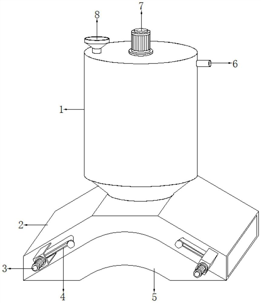
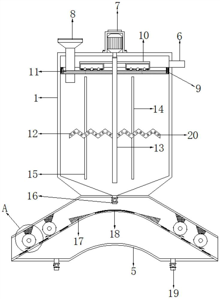
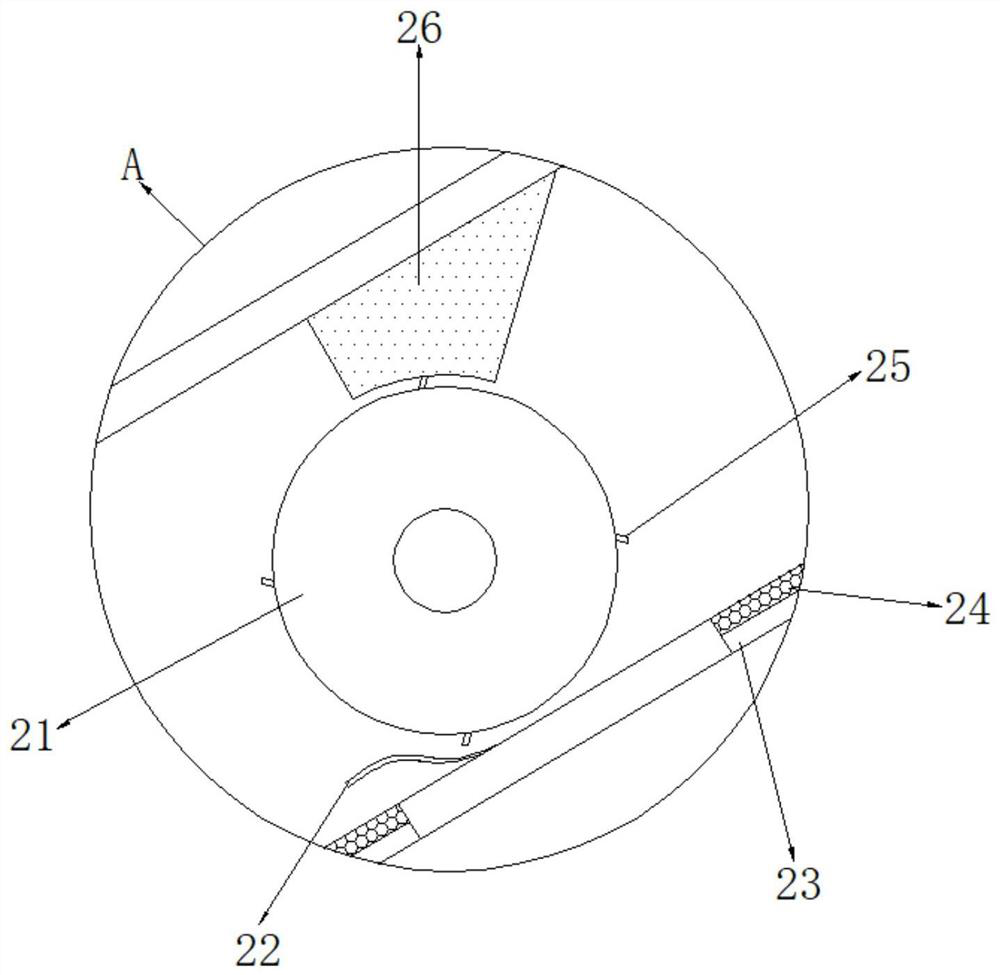
[0031] refer to Figure 1-4 , an energy-saving and environment-friendly sludge dewatering machine, comprising a treatment barrel 1, the inner wall of the treatment barrel 1 near the top is welded with a surrounding frame 9, and the inner wall of the surrounding frame 9 is connected with a sponge layer 11 by bolts, and the top side of the treatment barrel 1 The feed hopper 8 passing through the sponge layer 11 is connected by bolts, and the top of one side of the processing barrel 1 is welded with a flood pipe 6, and the middle position of the top of the processing barrel 1 is connected with a first motor 7 by bolts, and the first motor 7 The bottom of the output shaft extending into the processing barrel 1 is connected with a rotating shaft 13 by bolts, and the rotating shaft 13 passes through the inside of the sponge layer 11, and both sides of the outer wall of the rotating shaft 13 are welded with agitating blades 12, and the agitating blades 12 are bent. One side of the st...

Embodiment 2

[0041] refer to Figure 5 , an energy-saving and environment-friendly sludge dewatering machine. Compared with Embodiment 1, the bottom of the rotating shaft 13 is welded with a fixed shaft, and the outer wall of the fixed shaft is welded with a spiral blade 30, and the diameter of the spiral blade 30 is from top to bottom. slowing shrieking.

[0042] Working principle: Since the diameter of the spiral blade 30 gradually decreases from top to bottom, and the bottom of the processing barrel 1 is set in a funnel shape, when the sludge is introduced into the processing frame 2 through the discharge pipe 16, it can be driven and fixed by the rotating shaft 13 The shaft and the helical blade 30 rotate, and the helical blade 30 is used to drive the sludge to fall to increase the falling speed of the sludge.


PUM


Abstract

The invention discloses an energy-saving and environment-friendly sludge dewatering machine. The sludge dewatering machine comprises a treatment barrel, a surrounding frame is fixedly connected to theinner wall, close to the top, of the treatment barrel, a sponge layer is fixedly connected to the inner wall of the surrounding frame, a feeding hopper penetrating through the sponge layer is fixedlyconnected to one side of the top of the treatment barrel, and a water overflowing pipe is fixedly connected to the top of one side of the treatment barrel; a first motor is fixedly connected to the middle of the top of the treatment barrel, a rotating shaft is fixedly connected to the bottom, extending into the treatment barrel, of the output shaft of the first motor, the rotating shaft penetrates through the interior of the sponge layer, and stirring blades are fixedly connected to the two sides of the outer wall of the rotating shaft. Sludge is settled in the treatment barrel, water is discharged through the overflowing pipe, the flowing degree of water in the sludge is increased, a double-layer annular column groove structure is formed in the sludge, it is avoided that due to sludge accumulation, sewage is difficult to permeate out, then water in the sludge is extruded out, and the dewatering effect of the machine is improved.

Description

technical field [0001] The invention relates to the technical field of sludge treatment, in particular to an energy-saving and environment-friendly sludge dehydrator. Background technique [0002] Sludge refers to solid sedimentation substances such as sediment, particulate matter and floating matter produced when wastewater is treated by physical, chemical, physical chemical and biological methods. Sludge generally refers to thick matter between liquid and solid , can be transported by pump, according to the source of sludge, there are mainly domestic sewage sludge, industrial wastewater sludge and water supply sludge. Sludge is one of the important factors affecting the environment and air quality, and it needs to be treated. [0003] At present, when the sludge is being treated, it needs to be dehydrated to avoid the sludge concentration being thin and thick, which is not easy to handle. However, when the sludge enters the interior of the existing sludge dewatering device...

Claims


Application Information

Patent Timeline
IPC IPC(8): C02F11/121
CPCC02F11/121
Inventor 刘新
Owner 苏州浔宇新材料科技有限公司
Learn More