
Floating main shaft

A spindle and electric spindle technology, applied in the field of workpiece grinding, can solve the problems of electric spindle burnout, large riser and flash, under-grinding, etc., so as to avoid impact collision and protect the electric spindle from burning out.

Pending Publication Date: 2020-12-04
厦门达科塔机械有限公司
View PDF0 Cites 0 Cited by
  • Summary
  • Abstract
  • Description
  • Claims
  • Application Information

AI Technical Summary

Problems solved by technology

[0002] Most of the existing grinding equipment on the market is equipped with a non-floating spindle. If the riser and flash of the casting are large, this kind of hard grinding is easy to produce over-grinding and undergrinding
When over-grinding, the cutting force of the grinding wheel will increase instantaneously, causing the electric spindle to be overloaded with current and burn out the electric spindle; when under-grinding, the dimensional consistency of the casting after grinding cannot be guaranteed, and secondary rework is required, which is difficult Automated finishing of large batches

Method used


Image

  • Floating main shaft
  • Floating main shaft
  • Floating main shaft

Examples


Embodiment Construction

[0023] The present invention will be further described below in conjunction with the accompanying drawings and specific embodiments.

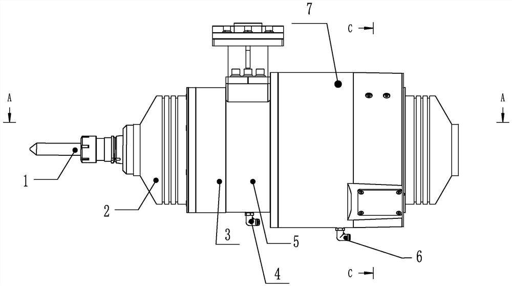
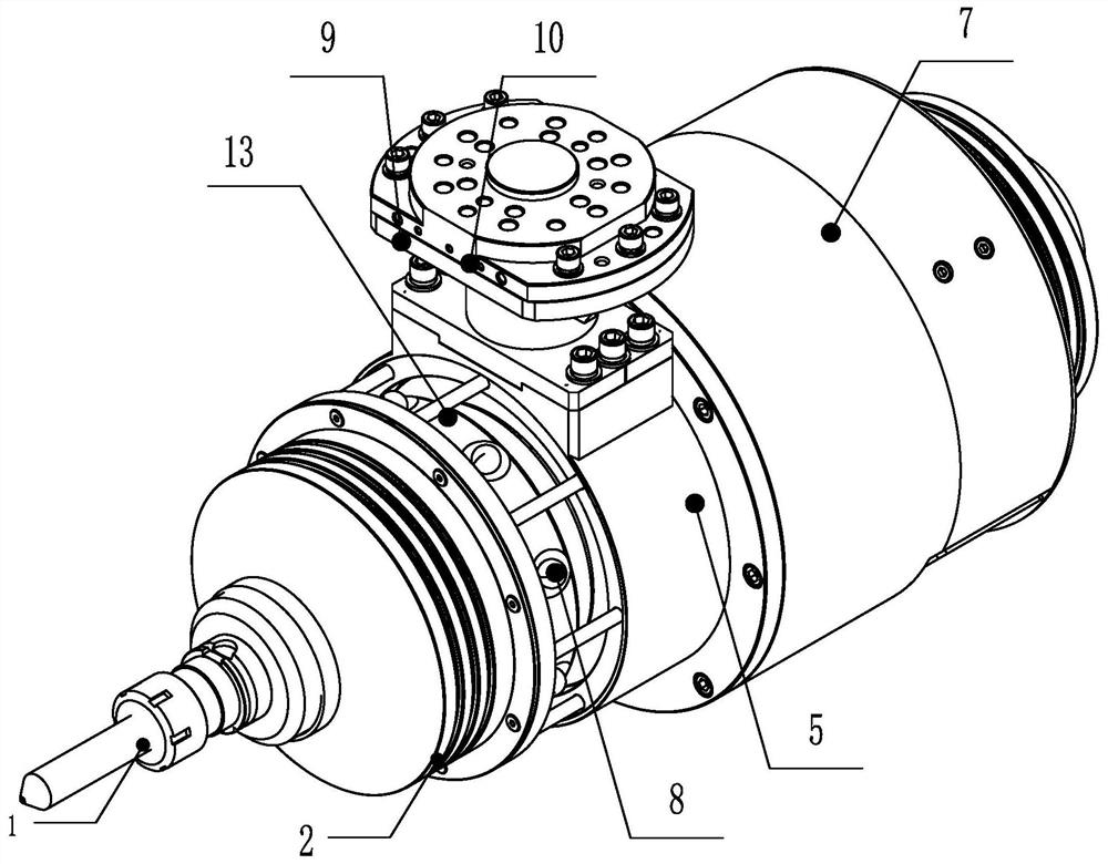
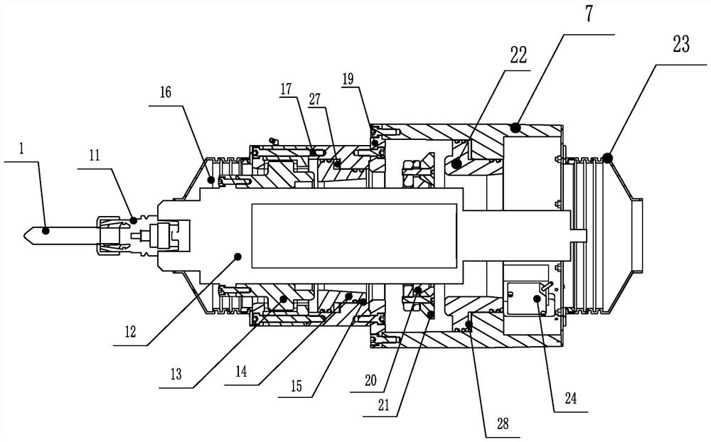
[0024] A floating spindle, see Figures 1 to 7 , including an electric spindle 12, the top of the electric spindle 12 is fixed with a grinding tool 1 through a tool handle 11, and one end of the electric spindle 12 fixed with the grinding tool 1 is provided with a protective sleeve, from the top of the electric spindle 12 to the end The direction of the end is coaxial with the electric main shaft 12 in turn, and the first protective sleeve 2, the end cover 29, the rotating frame 13, the second piston ring 14, the transition plate 19, the pressure ring 30, the expansion inner ring 20, the expansion outer ring Ring 21, first piston ring 22, displacement sensor 24, housing sealing plate 26, first flange 25 and second protective sleeve 23.

[0025] Specifically, the electric spindle 12 passes through a first piston ring 22, a displacement sensor 2...


PUM


Abstract

The invention provides a floating main shaft which comprises an electric main shaft. The electric main shaft penetrates through a first piston ring, a displacement sensor is arranged at the position close to the tail end of the electric main shaft, and a first shell is arranged outside the first piston ring. A sealing device is arranged between the first piston ring and the first shell, so that afirst sealing space is formed between the first piston ring and the first shell, and the sealing space communicates with a first vent hole. The electric main shaft deviates from the length direction of the electric spindle by a certain angle, so that the first piston ring moves in the direction close to the tail end of the electric spindle, and the displacement sensor detects the moving distance of the first piston ring. The first vent hole is ventilated, so that the first piston ring moves and resets close to the top end of the electric main shaft. By means of the technical scheme, impact andcollision to the electric main shaft in the workpiece grinding process can be avoided, and the electric main shaft is effectively protected.

Description

technical field [0001] The invention relates to the field of workpiece grinding, in particular to a floating spindle. Background technique [0002] The existing grinding equipment on the market is mostly equipped with a non-floating spindle. If the riser and flash of the casting are large, this kind of hard grinding is easy to produce over-grinding and undergrinding. When over-grinding, the cutting force of the grinding wheel will increase instantaneously, causing the electric spindle to be overloaded by current and burn out the electric spindle; when under-grinding, the dimensional consistency of the casting after grinding cannot be guaranteed, and secondary rework is required, which is difficult Realize high-volume automatic finishing. Contents of the invention [0003] The object of the present invention is to provide a floating spindle, which can avoid impact and collision with the electric spindle during workpiece grinding, and effectively protect the electric spindl...

Claims


Application Information

Patent Timeline
Patent Type & Authority Applications(China)
IPC IPC(8): B24B41/04
CPCB24B41/04
Inventor 陈成棋刘志伟张荣辉郭如琼
Owner 厦门达科塔机械有限公司
Learn More