
Isolation amplifier

A technology for isolation amplifiers and isolation layers, which is applied in the direction of improving amplifiers to reduce temperature/power supply voltage changes. It can solve problems such as difficult generation of triangular waves, complex circuits, and high power consumption. It achieves easy gain control, simple circuit structure, and low power consumption. Effect

Active Publication Date: 2020-12-01
SHANGHAI CHIPANALOG MICROELECTRONICS LTD
View PDF5 Cites 2 Cited by
  • Summary
  • Abstract
  • Description
  • Claims
  • Application Information

AI Technical Summary

Problems solved by technology

But this method also has some disadvantages: first, in order not to produce distortion, the peak-to-peak value of the triangular wave must completely cover the voltage swing at the input, and the rail-to-rail triangular wave is more difficult to generate
This method has very high accuracy, but its circuit complexity, high power consumption, low bandwidth and high cost

Method used


Image

  • Isolation amplifier
  • Isolation amplifier
  • Isolation amplifier

Examples


Embodiment Construction

[0041] Embodiments of the present disclosure will be described in detail below in conjunction with the accompanying drawings.

[0042] Embodiments of the present disclosure are described below through specific examples, and those skilled in the art can easily understand other advantages and effects of the present disclosure from the contents disclosed in this specification. Apparently, the described embodiments are only some of the embodiments of the present disclosure, not all of them. The present disclosure can also be implemented or applied through different specific implementation modes, and various modifications or changes can be made to the details in this specification based on different viewpoints and applications without departing from the spirit of the present disclosure. It should be noted that, in the case of no conflict, the following embodiments and features in the embodiments can be combined with each other. Based on the embodiments in the present disclosure, a...


PUM


Abstract

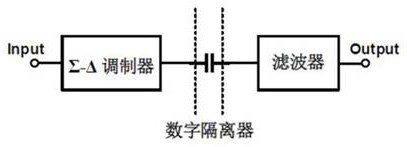
The invention provides an isolation amplifier which comprises a sending end, an isolation layer and a receiving end. The sending end is connected with the isolation layer and is used for amplifying the input signal of the isolation amplifier, modulating the amplified input signal of the isolation amplifier by adopting a closed-loop circuit, generating a modulation signal and sending the modulationsignal to the isolation layer; one end of the isolation layer is connected with the sending end, the other end is connected with the receiving end, and the isolation layer is used as a unique signaltransmission channel between the sending end and the receiving end to transmit modulation signals to the receiving end; the receiving end is connected with the isolation layer and is used for demodulating and amplifying the modulation signal and outputting an amplified signal; and the duty ratio of the modulation signal is in linear relation with the amplified input signal of the isolation amplifier. According to the invention, modulation is carried out by using a closed-loop method, errors are effectively suppressed, and the performance is improved. And meanwhile, the modulation circuit and the demodulation circuit adopt almost the same structure, so that the precision can be improved more effectively.

Description

technical field [0001] The invention belongs to the technical field of signal control transmission, and in particular relates to a high-precision isolation operational amplifier. Background technique [0002] An isolator is a component that converts an input signal to an output. The input, output and working power are isolated from each other, especially suitable for use with equipment and meters that require electrical isolation. Isolators, also known as signal isolators, are an important part of industrial control systems. [0003] Existing technology 1: The most original solution for isolating and transmitting analog signals is an optocoupler (Optocoupler), as attached figure 1 shown. The output terminal of the linear optocoupler is positively correlated with the current at the input terminal, but limited by the characteristics of the device itself, its accuracy is low, and its transmission characteristics will change significantly with temperature and aging factors, a...

Claims


Application Information

Patent Timeline
Patent Type & Authority Applications(China)
IPC IPC(8): H03F1/30
CPCH03F1/30
Inventor 陈炳天
Owner SHANGHAI CHIPANALOG MICROELECTRONICS LTD
Learn More