
Method for debugging main computing core by utilizing on-chip co-computing core

A technology for computing cores and debugging hosts, applied in general-purpose stored program computers, computing, computers, etc., and can solve problems such as low efficiency

Pending Publication Date: 2020-12-01
安徽芯纪元科技有限公司
View PDF0 Cites 1 Cited by
  • Summary
  • Abstract
  • Description
  • Claims
  • Application Information

AI Technical Summary

Problems solved by technology

[0003] The debugging system based on the in-circuit emulator has the following disadvantages: 1. All debugging communication packets need to be converted into the JTAG protocol and sent to the chip, and the JTAG protocol is a serial protocol, and the data is transmitted serially through TDI and TDO. The debugging operation of data transmission, such as memory import / export, will be very inefficient; 2. The in-circuit emulator is an external hardware device of the embedded system, which requires additional cost expenditure

Method used


Image

  • Method for debugging main computing core by utilizing on-chip co-computing core

Examples


Embodiment 1

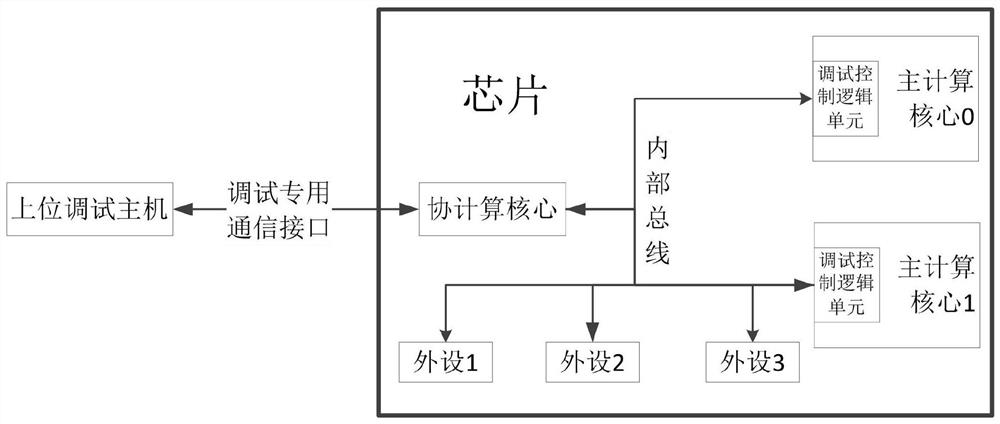
[0014] As the co-computing core that completes some auxiliary functions, it has the ability to control the on-chip peripheral resources, control the Ethernet interface, UART interface or other communication interfaces to communicate with the host computer. Internally, the co-computing core connects each peripheral device and each main computing core through an internal bus; externally, it controls the peripheral devices communicating with the upper computer, such as Ethernet interface, UART interface, etc., such as figure 1 shown. The present invention designs a method for debugging the main computing core by utilizing the on-chip co-computing core based on the characteristics of the co-computing core itself.

[0015] The co-computing core communicates with the debugging host through a communication interface used solely for debugging, analyzes the debugging commands sent by the debugging host, and converts them into operation sequences on the internal bus of the chip, and con...


PUM


Abstract

The invention provides a method for debugging a main computing core by utilizing an on-chip co-computing core. The co-computing core communicates with the debugging host through a communication interface independently used for debugging, analyzes a debugging command sent by the debugging host, converts the debugging command into an operation sequence on an internal bus of the chip, and controls the main computer core to execute a debugging action or access other on-chip resources to complete the debugging command; after the debugging task is executed, the co-computing core reports an executionresult of the debugging command to the debugging host; the co-compute core may also monitor the state of the primary compute core and actively report the event to the debug host when the state of theprimary compute core changes. The debugging method is completely different from an existing debugging technology, the debugging communication rate of the debugging method is far higher than that of atraditional debugging communication rate based on a JTAG bus, an upper computer directly conducts chip debugging through a communication interface of a chip, and extra hardware equipment is not needed any more.

Description

technical field [0001] The invention relates to the technical field of embedded system debugging, in particular to a method for debugging a main computing core by using an on-chip co-computing core. Background technique [0002] The in-circuit emulator debugs the embedded system through the JTAG bus, which is a common means of modern debugging systems. One end of the in-circuit emulator is connected to the debugging host (usually an ordinary PC) through a USB or Ethernet cable, and the other end is connected to the embedded board through the JTAG bus. JTAG is an international standard test protocol, mainly used for chip internal testing. Currently, most processors on the market support the JTAG protocol. An in-circuit emulator is a small embedded system, generally including a small CPU chip and an FPGA chip. The CPU is used to communicate with the debugging host through the USB or Ethernet cable. The software running on the CPU analyzes the debugging communication protoco...

Claims


Application Information

Patent Timeline
IPC IPC(8): G06F11/36G06F15/78
CPCG06F11/3652G06F11/3656G06F15/7807
Inventor 林广栋周乐陈金忠耿锐赵纪堂刘谷洪一
Owner 安徽芯纪元科技有限公司
Learn More