
Air guide assembly of air conditioner

A technology of air guide components and air conditioners, which is applied in air conditioning systems, space heating and ventilation, space heating and ventilation details, etc., and can solve problems such as poor controllability of air flow and condensation on air guide plates

Pending Publication Date: 2020-12-01
QINGDAO HAIER AIR CONDITIONING ELECTRONICS CO LTD +1
View PDF0 Cites 1 Cited by
  • Summary
  • Abstract
  • Description
  • Claims
  • Application Information

AI Technical Summary

Problems solved by technology

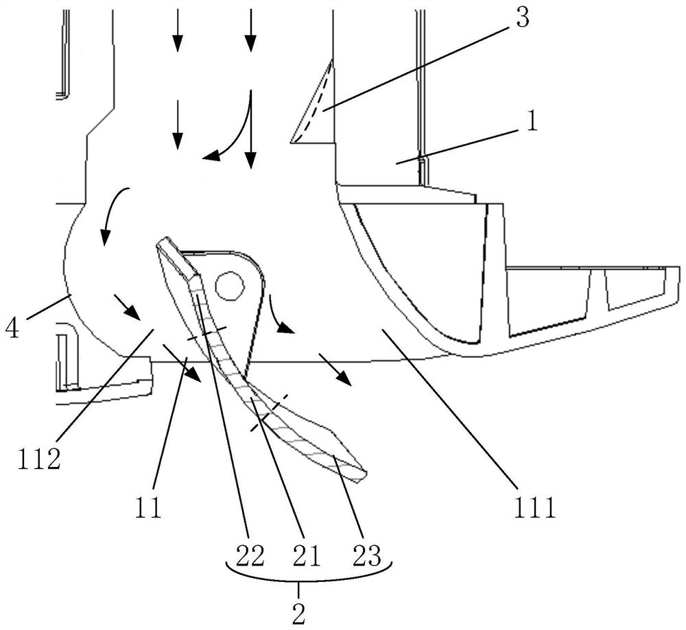
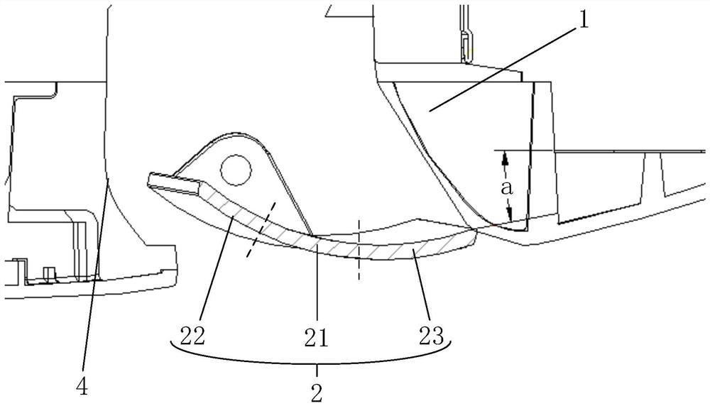
[0005] In order to solve the above-mentioned problems in the prior art, that is, in order to solve the problems of condensation on the air deflector and poor controllability of airflow caused by the unbalanced air outlet on both sides of the air deflector in the existing air conditioner, the present invention provides an air conditioner The air guide assembly of the air conditioner, the air conditioner includes a housing and an air outlet provided on the housing, the air guide assembly includes an air guide plate connected to the housing in a rotational manner, and the air guide plate Including a first side close to the housing and a second side away from the housing in an open state, and when the air deflector is opened, the air deflector divides the air outlet to be close to The windward part of the windward side of the wind deflector and the leeward part of the leeward side of the wind deflector, the wind deflector can guide the airflow in the housing to flow to the outside through the windward part, so The part of the wind deflector close to the first side is an arc structure, and the arc structure expands and extends toward the windward side of the wind deflector, so as to increase the air flow of the leeward part, and the wind deflector The assembly also includes a wind guiding protrusion arranged in the housing, and the wind guiding protrusion is configured to guide part of the airflow in the housing to flow toward the windward side of the arc structure when the wind guiding plate is opened.

Method used


Image

  • Air guide assembly of air conditioner
  • Air guide assembly of air conditioner
  • Air guide assembly of air conditioner

Examples


Embodiment Construction

[0025] Those skilled in the art should understand that these embodiments are only used to explain the technical principles of the present invention, and are not intended to limit the protection scope of the present invention. Those skilled in the art can make adjustments as needed so as to adapt to specific applications. For example, although the air conditioner shown in the accompanying drawings of the present invention is a built-in air conditioner, this is not limiting. In fact, the air guide assembly of the present invention can be applied to any air conditioner with the same air guide requirements On, such as wall-mounted air conditioners, ceiling-mounted air conditioners, etc.

[0026] It should be noted that, in the description of the present invention, terms such as "upper", "lower", "vertical", "horizontal", "inner", "outer" and other indicated directions or positional relationships are based on the accompanying drawings The directions or positional relationships sho...


PUM

PropertyMeasurementUnit
Extended heightaaaaaaaaaa

Abstract

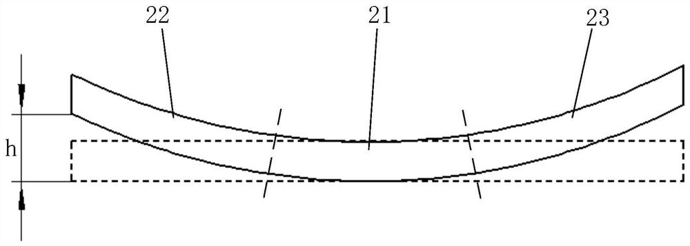
The invention belongs to the technical field of air conditioners, and particularly relates to an air guide assembly of an air conditioner. The air guide assembly of the air conditioner comprises an air guide plate, an air guide protrusion and an air guide rail. The air guide plate comprises a first arc-shaped structure and a second arc-shaped structure. The first arc-shaped structure can expand the air outlet space of the leeward side of the air guide plate, the air guide protrusion can guide part of air flow in the shell to flow to the first arc-shaped structure, and the air flow of the leeward side of the air guide plate is increased. The air guide rail can enable airflow to flow along the leeward side of the air guide plate when the airflow flows through the leeward side of the air guide plate. The second arc-shaped structure can increase the air outlet space of the windward side of the air guide plate under the condition that the air guide angle of the air conditioner is not changed. By means of the arrangement, airflow on the windward side and the leeward side of the air guide plate tends to be in a balanced flowing state, the air outlet effect of the air conditioner is optimized, the large temperature difference between the windward side and the leeward side of the air guide plate is avoided, the condensation condition of the air guide plate is improved, and the user experience is improved.

Description

technical field [0001] The invention belongs to the technical field of air conditioners, and in particular relates to an air guide assembly of an air conditioner. Background technique [0002] The position of the air outlet of the air conditioner is usually provided with an air deflector, and the user can control the flow direction of the airflow at the air outlet by controlling the opening angle of the air deflector, so that the airflow of the air conditioner can flow in the direction expected by the user and improve the indoor environment. temperature environment. [0003] In this case, since most of the airflow of the air conditioner flows through the windward side of the wind deflector, less airflow flows through the leeward side of the wind deflector. On the one hand, the above situation may lead to a large temperature difference between the windward side and the leeward side of the air deflector when the airflow blown out by the air conditioner is greatly different fr...

Claims


Application Information

Patent Timeline
IPC IPC(8): F24F13/14F24F13/08F24F13/22F24F1/0014
CPCF24F13/14F24F13/08F24F13/081F24F13/22F24F1/0014F24F2013/221
Inventor 李文波宋强刘景升刘江彬孟庆良谭雪艳
Owner QINGDAO HAIER AIR CONDITIONING ELECTRONICS CO LTD
Learn More