Bearing bracket

A bearing bracket, No. 1 technology, applied to the rigid bracket of bearing components, bearing elements, shafts and bearings, etc., can solve the problems of easy loosening of bearing brackets, inconvenient replacement of bearings, and increased production costs of processing plants, etc., to achieve convenient disassembly And the effect of fixing, saving labor force and reducing production cost

Inactive Publication Date: 2020-12-01
湖南新达微轴承有限公司
View PDF1 Cites 1 Cited by
  • Summary
  • Abstract
  • Description
  • Claims
  • Application Information

AI Technical Summary

Problems solved by technology

[0002] Bearing brackets are widely used in automobiles, aerospace, and machinery manufacturing plants, especially bearing brackets for rolling and pressing workpieces, which have the advantages of convenient installation, simple structure, and easy operation; the bearing of the existing public patent CN109973530A There are still certain disadvantages in the use of the bracket. First, when the existing bearing bracket is fixed on the mechanical equipment for use, its fixed structure is too simple, which causes the bearing bracket to loosen easily and affects the normal use of the mechanical equipment; second, After the existing bearing bracket is damaged and aged, it is inconvenient to replace the bearing. It is necessary to directly replace the whole bearing bracket in order to continue to use the mechanical equipment, which leads to an increase in the production cost of the processing plant; third, when the existing bearing bracket is adjusted , mostly manual adjustment, the accuracy of manual adjustment is not high, and it consumes manual labor. Therefore, we propose a bearing bracket

Method used


Image

  • Bearing bracket
  • Bearing bracket
  • Bearing bracket

Examples


Embodiment 1

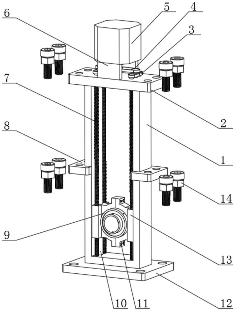
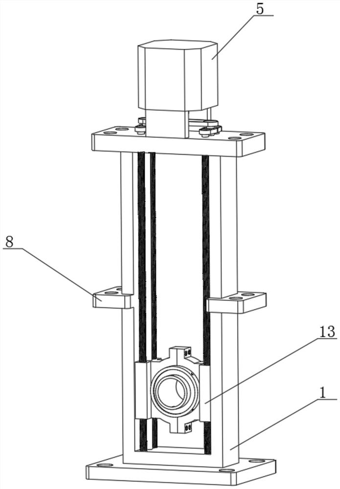
[0028] Such as figure 1 , 3 As shown, a bearing bracket includes a bracket main body 1, a fixed bottom plate 12 is provided on the outer surface of the lower end of the bracket main body 1, a fixing part 8 is arranged on the side end outer surface of the bracket main body 1, and a screw group is arranged on the side end of the fixing part 8 14. The outer surface of the upper end of the bracket main body 1 is provided with a limit cover plate 2, the outer surface of the upper end of the limit cover plate 2 is provided with a fixed plate 6, and the outer surface of the upper end of the fixed plate 6 is provided with a motor 5, and the model of the motor 5 is 42HS02. The upper end outer surface of support main body 1 is provided with No. 1 transmission belt 3 corresponding to the lower end of motor 5, and the upper end outer surface of No. 1 transmission belt 3 is provided with No. 1 transmission wheel 4, and the inner side outer surface of support main body 1 is provided with sl...

Embodiment 2

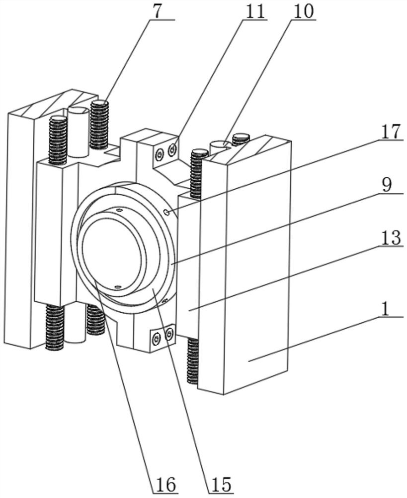
[0030] On the basis of Example 1, as figure 2 , 4 , 5, the lower end of the threaded screw rod 7 is embedded in the inner side of the bracket main body 1, and the two are flexibly connected, and the upper end of the threaded screw rod 7 runs through the limit cover plate 2, and the two are flexibly connected , the number of threaded screw rods 7 is four, and they are arranged in a symmetrical relationship. The outer surface of the left end of the slide bar 10 is attached to the inner outer surface of the bracket main body 1, and the two are fixedly connected. The rotation of the bar 7 can make the slide block 13 slide on the slide bar 10, the slide block 13 is movably connected with the bracket main body 1, the slide bar 10 and the threaded screw rod 7 all run through the slide block 13, and the slide bar 10 and the threaded wire All are movable connection between bar 7 and slide block 13, and the quantity of slide bar 10 and slide block 13 is two groups, and is arranged sym...

Embodiment 3

[0032] On the basis of embodiment one and embodiment two, such as figure 2 , 4, shown in 5, 6, the upper end of connecting shaft is provided with No. 4 transmission wheel 21, and is movable connection between the two, the outer surface of No. 2 transmission wheel 19 and No. 4 transmission wheel 21 is provided with No. 1 transmission belt 3, and three There is a transmission connection between them, the No. 1 transmission wheel 4 is arranged on the upper end of the No. 4 transmission wheel 21, and is fixedly connected between the two, and the lower end of the motor 5 is provided with a connecting shaft, and is a movable connection between the two, and the connecting shaft The lower end of the drive wheel 20 is provided with a No. 3 drive wheel 20, and the two are fixedly connected. The transmission force is generated by the motor 5 and the No. 3 drive wheel 20. The outer surface of the No. 3 drive wheel 20 and the No. 1 drive wheel 4 is provided with a No. 2 drive wheel. Tran...


PUM


Abstract

The invention relates to the technical field of bearings, and discloses a bearing bracket. The bearing bracket comprises a bracket body, a fixed bottom plate is arranged on the outer surface of the lower end of the bracket body, a fixing piece is arranged on the outer surface of the side end of the bracket body, screw sets are arranged at the side ends of the fixing piece, a limiting cover plate is arranged on the outer surface of the upper end of the bracket body, a fixing plate is arranged on the outer surface of the upper end of the limiting cover plate, a motor is arranged on the outer surface of the upper end of the fixing plate, and a first transmission belt is arranged at the position, corresponding to the lower end of the motor, of the outer surface of the upper end of the bracketbody. According to the bearing bracket, the fixing piece, the limiting cover plate and the screw set are matched with the fixed bottom plate to fix the bracket body to mechanical equipment; through triple fixing, stability is improved, through cooperation of the motor, a threaded lead screw and a sliding rod, the height position of a bearing can be adjusted instead of manual work, precision is better, through cooperation of a sliding block, a fixing screw and a limiting ring, a user can replace the bearing conveniently, and production cost is reduced.

Description

technical field [0001] The invention relates to the technical field of bearings, in particular to a bearing bracket. Background technique [0002] Bearing brackets are widely used in automobiles, aerospace, and machinery manufacturing plants, especially bearing brackets for rolling and pressing workpieces, which have the advantages of convenient installation, simple structure, and easy operation; the bearing of the existing public patent CN109973530A There are still certain disadvantages in the use of the bracket. First, when the existing bearing bracket is fixed on the mechanical equipment for use, its fixed structure is too simple, which causes the bearing bracket to loosen easily and affects the normal use of the mechanical equipment; second, After the existing bearing bracket is damaged and aged, it is inconvenient to replace the bearing. It is necessary to directly replace the whole bearing bracket in order to continue to use the mechanical equipment, resulting in an in...

Claims


Application Information

Patent Timeline
Patent Type & Authority Applications(China)
IPC IPC(8): F16C35/04F16C35/06
CPCF16C35/04F16C35/06
Inventor 罗清华朱立生刘洪军
Owner 湖南新达微轴承有限公司
Why Eureka
Try Eureka