
Suspension connecting joint for large-span cantilever steel truss and construction method thereof

A technology of long-span cantilevering and connecting nodes, which is applied in the direction of load-bearing elongated structural members, special structures, buildings, etc., and can solve problems such as difficulty in guaranteeing construction accuracy, high cost of supporting tire frames, and complex node spaces. Achieve the effects of low design and construction difficulty, convenient pre-arching value, and high safety redundancy

Active Publication Date: 2020-12-01
THE THIRD CONSTR OF CHINA CONSTR FIRST GROUP +1
View PDF4 Cites 11 Cited by
  • Summary
  • Abstract
  • Description
  • Claims
  • Application Information

AI Technical Summary

Problems solved by technology

[0005] The invention provides an adjustable steel tie rod for a suspension system of a large-span cantilevered steel structure, which is used to solve the problems of cumbersome installation of the existing large-span cantilevered steel structure suspension system, high cost of the support tire frame, complex node space, and safety. Technical problems such as low redundancy, long construction period, low efficiency, and difficulty in guaranteeing construction accuracy

Method used


Image

  • Suspension connecting joint for large-span cantilever steel truss and construction method thereof
  • Suspension connecting joint for large-span cantilever steel truss and construction method thereof
  • Suspension connecting joint for large-span cantilever steel truss and construction method thereof

Examples


Embodiment Construction

[0038] The technical solutions of the present invention are described in detail below through the examples, and the following examples are only exemplary, and can only be used to explain and illustrate the technical solutions of the present invention, but cannot be construed as limitations to the technical solutions of the present invention.

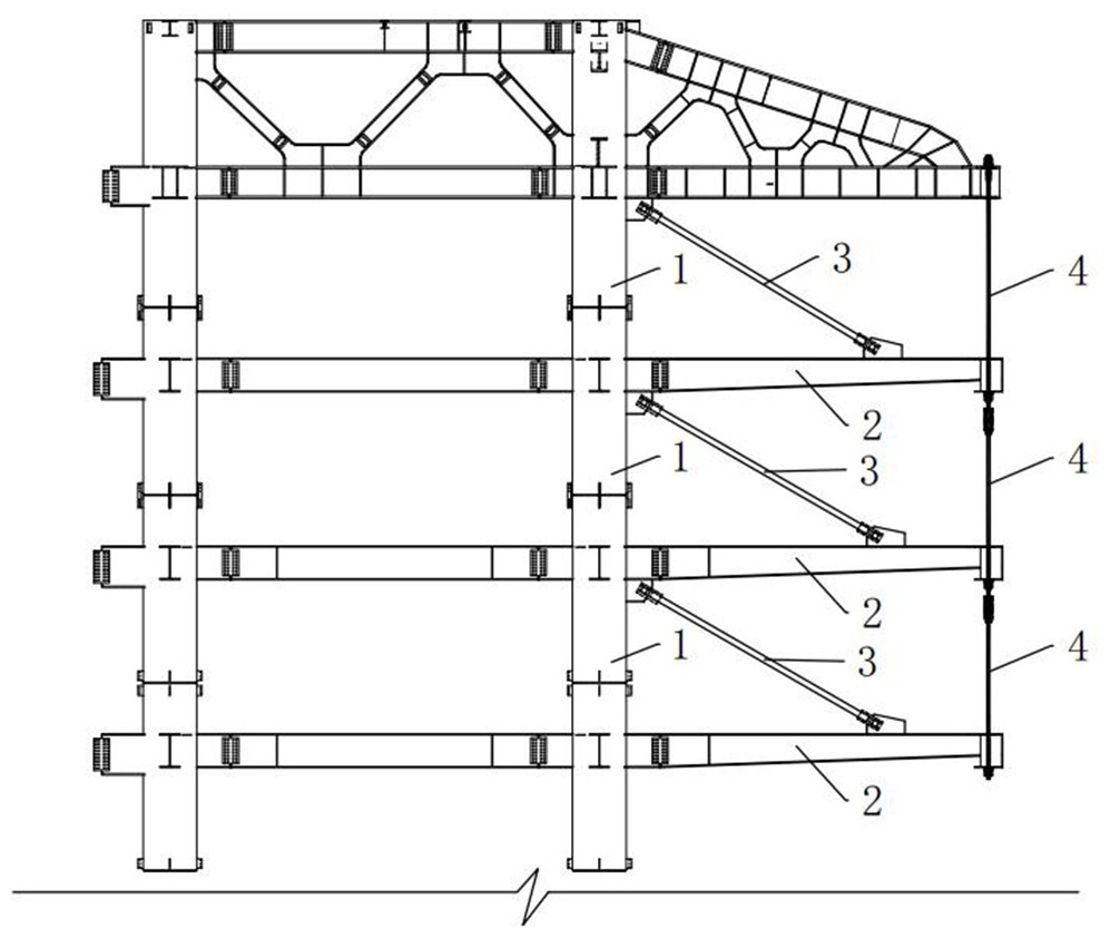
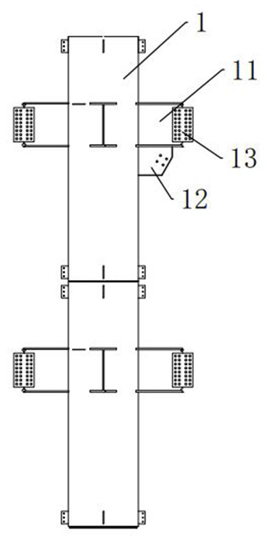
[0039] Such as figure 1 , a suspension connection node for a large-span cantilevered steel truss, including a steel pipe column 1, a cantilevered main beam 2, a temporary steel tie rod 3 and a fixed steel tie rod 4, such as figure 2 , the steel pipe column 1 is arranged vertically on the edge of the main structure, the side end of the steel pipe column 1 is fixedly welded with a steel corbel 11, and the bottom end of the steel corbel 11 is fixedly provided with a vertical column ear plate 12, and the column ear plate 12 is in the shape of a perforated plate, and the end of the steel corbel 11 away from the steel pipe column 1 is provide...


PUM


Abstract

The invention discloses a suspension connecting joint for a large-span cantilever steel truss and a construction method of the suspension connecting joint. The suspension connecting joint comprises steel pipe columns, cantilever main beams, temporary steel pull rods and fixing steel pull rods. Steel corbels are arranged at the side ends of the steel pipe columns, vertical column lug plates are arranged at the bottom ends of the steel corbels, and web plates are arranged at the ends, far away from the steel pipe columns, of the steel corbels. One end of each cantilever main beam is connected tothe corresponding web plate, and beam joints are arranged at the ends, far away from the steel pipe columns, of the cantilever main beams and used for being connected with edge beams which are perpendicular to the cantilever main beams. A beam lug plate is fixedly arranged at the top end of each cantilever main beam. Connecting plates are fixedly arranged at the two ends of each temporary steel pull rod, the two connecting plates of each temporary steel pull rod are fixedly connected with the corresponding column lug plate and the corresponding beam lug plate. The structure is constructed inthe forward direction from bottom to top, the temporary steel pull rods are adopted to assist in layer-by-layer installation and adjustment of the cantilever main beams, component hoisting is furtherprotected, an operator has a working face and safety protection, the suspension structure is constructed layer by layer from bottom to top in sequence, component installation is facilitated, and the efficiency is improved.

Description

technical field [0001] The invention belongs to the field of large-span cantilevered steel truss suspension structures, and particularly relates to a large-span cantilevered steel truss suspension connection node and a construction method thereof. Background technique [0002] With the development of the construction industry, more and more architects have broken the tradition and pursued the design of houses with large overhangs, large spaces, and high permeability. The structural system of steel trusses on the whole floor of the roof and high-strength steel rods at the ends of the trusses suspends three-story large cantilevered steel beams and floor slabs. The cross-section is optimized, and at the same time, it satisfies the permeability of the building's interior space and facade, creating a large column-free space for the interior. [0003] According to the mechanical characteristics of the suspended structure system, the traditional construction sequence is to complet...

Claims


Application Information

Patent Timeline
Patent Type & Authority Applications(China)
IPC IPC(8): E04B1/34E04B1/342E04B1/58
CPCE04B1/34E04B1/342E04B1/58E04B1/5812E04B2001/2415E04B2001/2418E04B2001/2406E04B2001/2442E04B2001/2448E04B2001/2457E04B2001/2496E04B1/2403E04B1/3527E04C2003/0491E04C3/11E04C3/08
Inventor 王欣鹏张奎郑永超张万宏刘大伟罗德俊张楠冉星晨胡祥松唐远进
Owner THE THIRD CONSTR OF CHINA CONSTR FIRST GROUP
Learn More