Spiral core-pulling mold for transmission sleeve

A transmission sleeve and spiral technology, applied in the field of spiral core-pulling molds, can solve the problems of slow cooling speed, slow forming, and poor precision, and achieve the effects of high precision, easy rotation, and guaranteed size

Pending Publication Date: 2020-12-01
NINGBO HENGHE PRECISION INDUSTRY CO LTD
View PDF0 Cites 2 Cited by
  • Summary
  • Abstract
  • Description
  • Claims
  • Application Information

AI Technical Summary

Problems solved by technology

For products with a threaded structure inside, it is usually necessary to add a threaded core in the mold core, but the common threaded core is set in a solid shape, and there is no cooling water channel inside, so the cooling rate is prone to occur during the injection molding process And the problem of slow molding and poor precision

Method used


Image

  • Spiral core-pulling mold for transmission sleeve
  • Spiral core-pulling mold for transmission sleeve
  • Spiral core-pulling mold for transmission sleeve

Examples


Embodiment 1

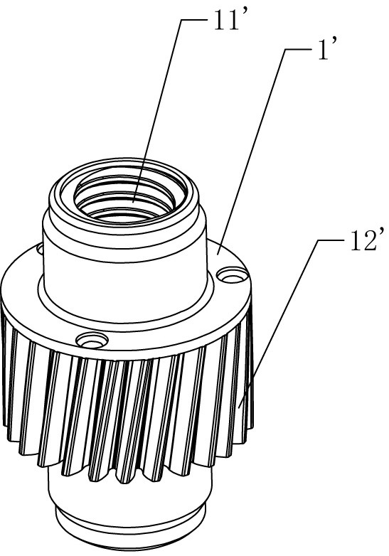
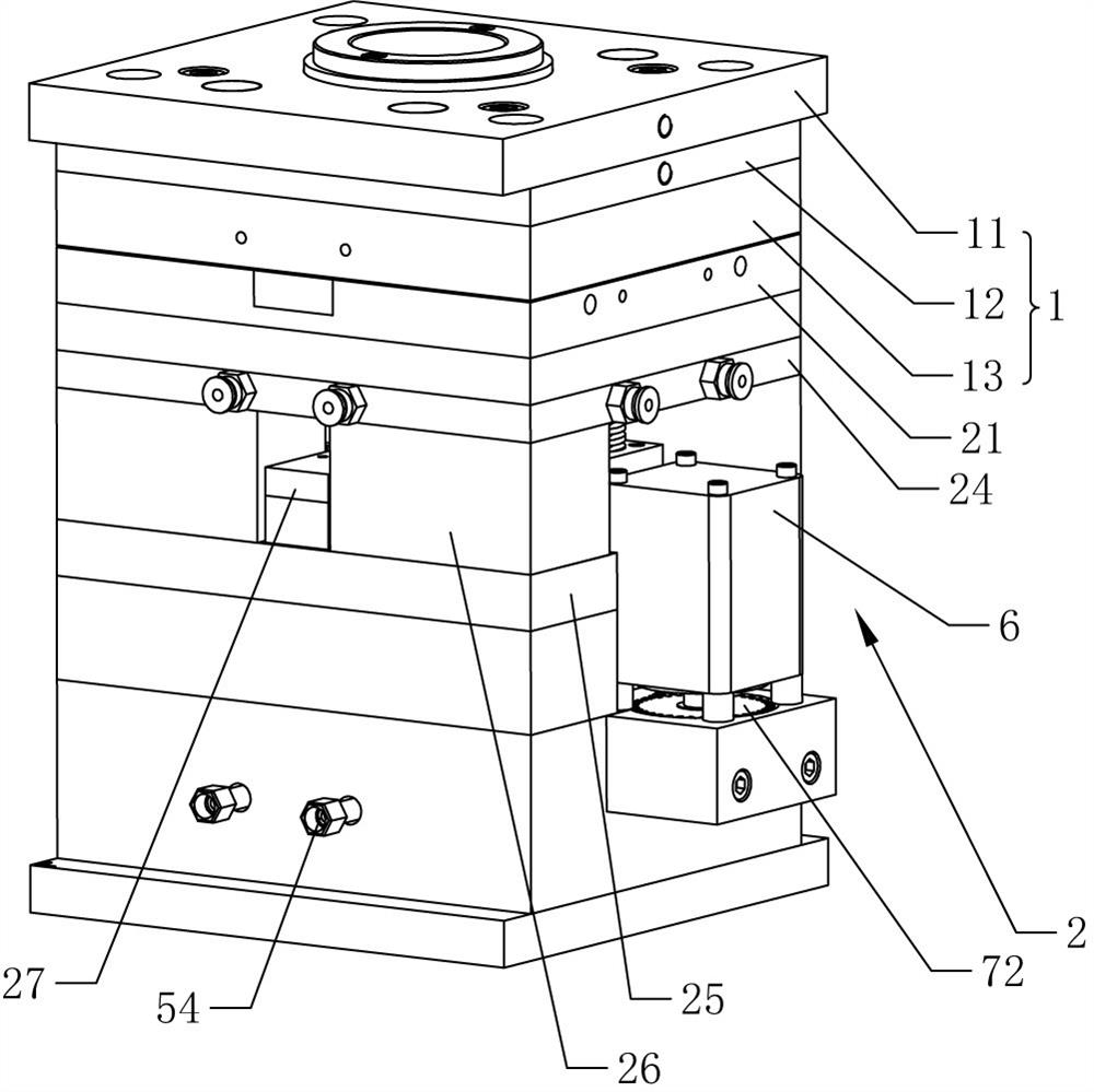
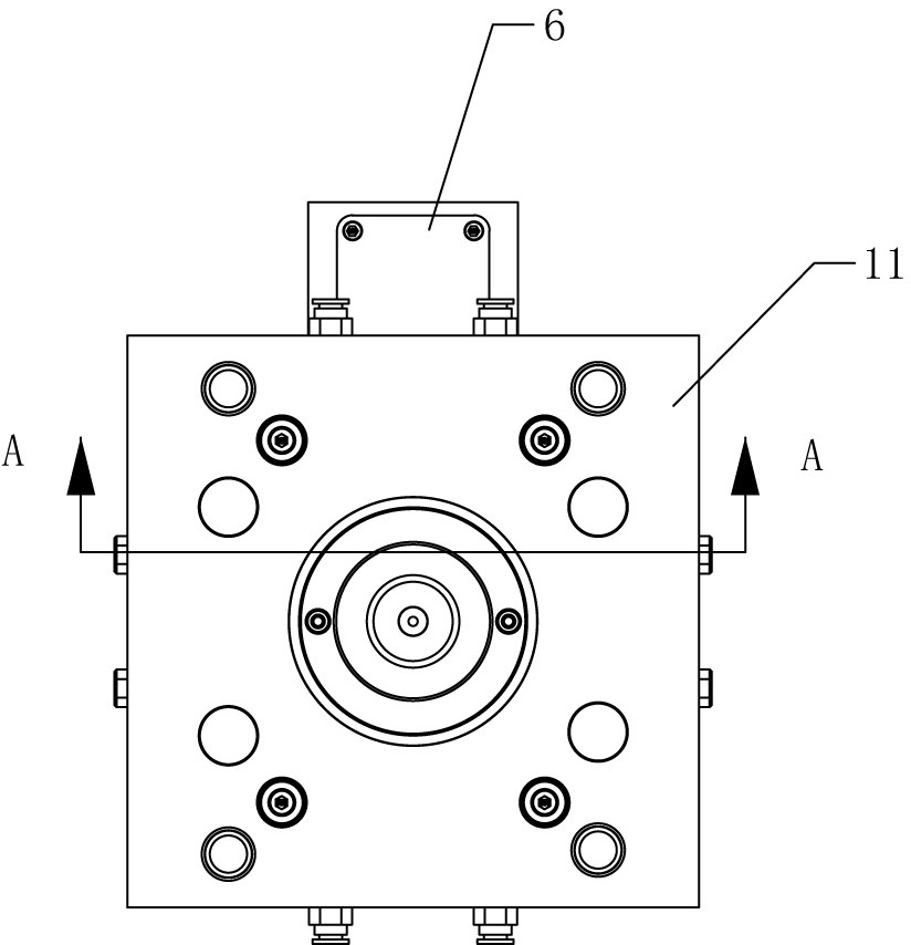
[0046] A spiral core-pulling die for transmission sleeves, such as figure 1 It is a schematic diagram of the structural relationship of the transmission sleeve in the prior art, such as Figure 2-9 Shown is a schematic diagram of the mold structure relationship, including an upper mold assembly 1 and a lower mold assembly 2, four stations are arranged between the upper mold assembly 1 and the lower mold assembly 2, and the upper mold assembly 1 is from top to bottom The upper top plate 11, the feeding plate 12 and the movable platen 13 are arranged in sequence, the lower mold assembly 2 includes a fixed platen 21 arranged on the top, and four upper mold cores 3 are arranged on the movable platen 13, and the inner part of the feeding plate 12 A feed pipeline is provided, and the upper mold core 3 is provided with a feed passage 31 connected to the feed pipeline. The fixed template 21 is correspondingly provided with a lower mold core 22 and a lower mold insert 23. The upper mol...

Embodiment 2

[0058] A threaded core-pulling die for transmission sleeves, such as Figure 10 As shown, the difference between this embodiment and the above-mentioned embodiments is that a water baffle 55 is arranged in the cooling water channel 42, and the water baffle 55 separates the water inlet 44 and the water outlet 45, and when the water flows through the water inlet 44 into the cooling When inside the water channel 42, under the action of the baffle plate 55, the water flow can flow up to the top and then flow down to form an inverted U-shaped water path, so as to ensure sufficient cooling effect and avoid the straight flow of water flow to a certain extent straight out.


PUM


Abstract

The invention discloses a spiral core-pulling mold for a transmission sleeve. The die comprises an upper die assembly and a lower die assembly, the upper die assembly is provided with a movable die plate, the lower die assembly is provided with a fixed die plate, the movable die plate is provided with an upper die core, the fixed die plate is provided with a lower die core and a lower die insert,a threaded rod is further arranged in the lower die assembly and provided with an upper external thread, and the lower die insert is provided with a through hole; the threaded rod penetrates through the through hole; and a cooling water channel is formed in the threaded rod, a water inlet and a water outlet are formed in the side wall of the threaded rod, and a water conveying component is arranged in the lower die assembly and communicated with the water inlet and the water outlet. The lower die assembly is provided with a driving mechanism; and the lower die assembly comprises an ejector block, the ejector block is provided with an ejector sleeve, and the ejector sleeve sleeves the outer wall of the threaded rod. The spiral core-pulling mold has the following advantages and effects thatthe scheme utilizes a new mechanical structure, and has the effects of rapid molding and high precision.

Description

technical field [0001] The invention relates to the technical field of molds, in particular to a spiral core-pulling mold used for a transmission sleeve. Background technique [0002] With the development of the mold industry and the continuous innovation of technology, the mold structure converts general manual operation into full mechanical movement, overcomes the uncertain factors brought about by manual operation, and thus ensures high stability of product size, high precision requirements, and appearance requirements. Long time mass production requirements. For products with a threaded structure inside, it is usually necessary to add a threaded core in the mold core, but the common threaded core is set in a solid shape, and there is no cooling water channel inside, so the cooling rate is prone to occur during the injection molding process And the problem of slow molding and poor precision. [0003] There is an existing automobile transmission sleeve, such as figure 1...

Claims


Application Information

Patent Timeline
Patent Type & Authority Applications(China)
IPC IPC(8): B29C45/26B29C45/44B29C45/73B29L1/00
CPCB29C45/2608B29C45/262B29C45/7312B29L2001/00
Inventor 吴雅琪赵明洋
Owner NINGBO HENGHE PRECISION INDUSTRY CO LTD
Why Eureka
Try Eureka