Cement road side edge perforating machine for highway guardrail installation
A road guardrail and installation technology, applied in the field of drilling machines, can solve the problems of injury and manpower consumption, and achieve the effects of convenient operation, ensuring safety and saving manpower
- Summary
- Abstract
- Description
- Claims
- Application Information
AI Technical Summary
Problems solved by technology
Method used
Image

Examples
Embodiment 1
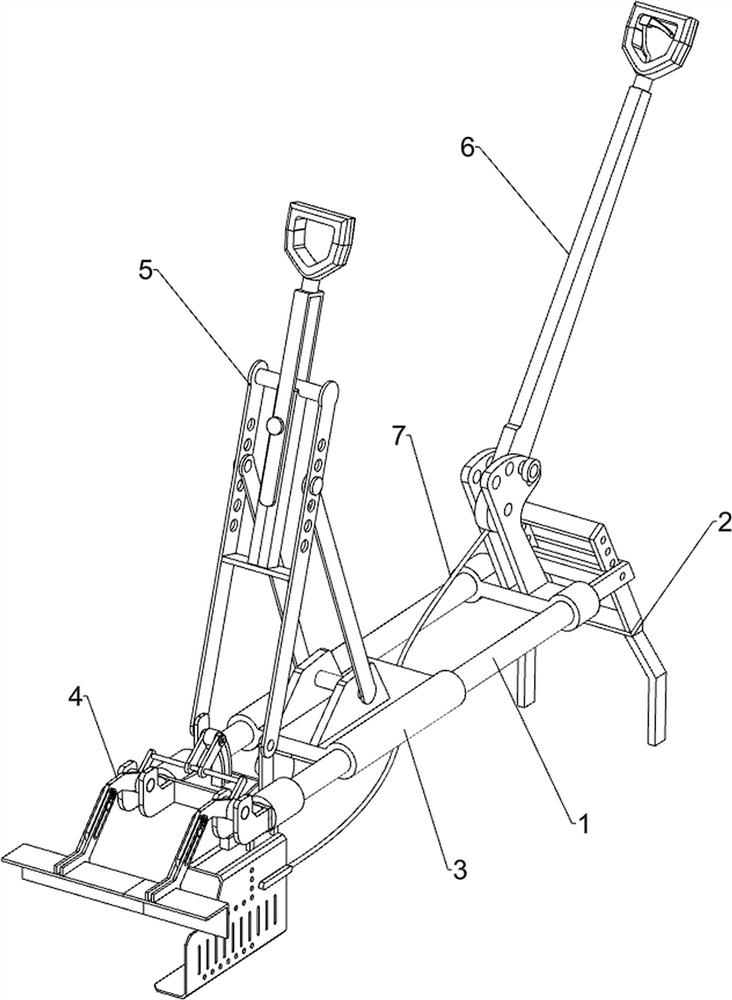
[0027] A cement road side punching machine for highway guardrail installation, such as Figure 1-4 As shown, it includes a guide frame 1, a rear support frame 2, a drilling machine fixing mechanism 3 and a front positioning mechanism 4. The rear support frame 2 is installed on the rear side of the guide frame 1, and the rear support frame 2 is an adjustable setting. The guide frame 1 A drilling machine fixing mechanism 3 and a front positioning mechanism 4 are arranged on the top.
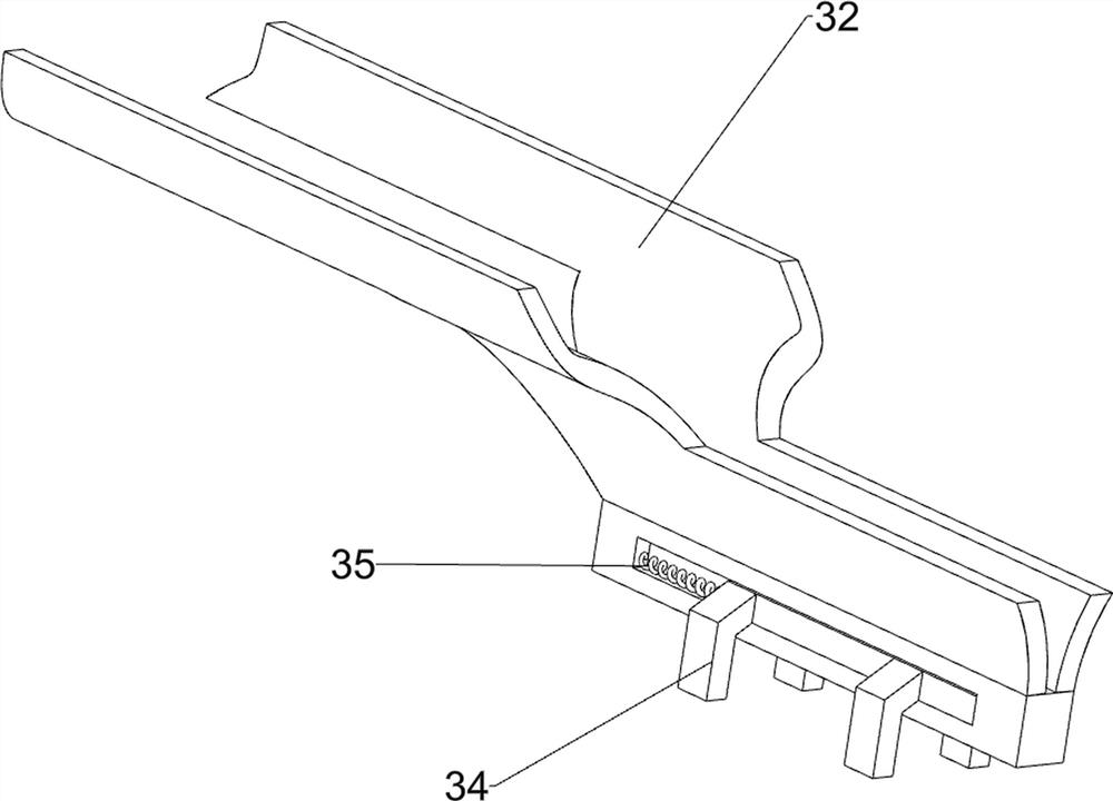
[0028] Drilling machine fixing mechanism 3 comprises the first slide seat 31, slide rail 32, mounting plate 33, slide block 34 and buffer spring 35, and the guide frame 1 is slidably connected with the first slide seat 31, the bottom of the first slide seat 31 A slide rail 32 is connected, a slide block 34 is slidably connected to the slide rail 32 , a mounting plate 33 is connected to the slide block 34 , and a buffer spring 35 is connected between the slide block 34 and the slide rail 32 .
[00...
Embodiment 2
[0032] On the basis of Example 1, such as Figure 5 As shown, a propulsion mechanism 5 is also included, and the propulsion mechanism 5 includes a fixed seat 51, a second swing frame 52, a connecting rod 53, a sliding frame 54, a front handle 55 and a fastening bolt 56, and the front side of the guide frame 1 is connected with The fixed seat 51 is hingedly connected to the second swing frame 52, the top of the first sliding seat 31 is hingedly connected to a connecting rod 53, the connecting rod 53 is hingedly connected to the second swing frame 52, and the second swing frame 52 is slidably connected. There is a sliding frame 54, the top of the sliding frame 54 is connected with a front grip 55, and the sliding frame 54 is threaded with a fastening bolt 56, and the fastening bolt 56 is used to fix the sliding frame 54.
[0033] When the first sliding seat 31 needs to be pulled to move forward, the front grip 55 can be pulled to move forward to drive the sliding frame 54 to mov...
Embodiment 3
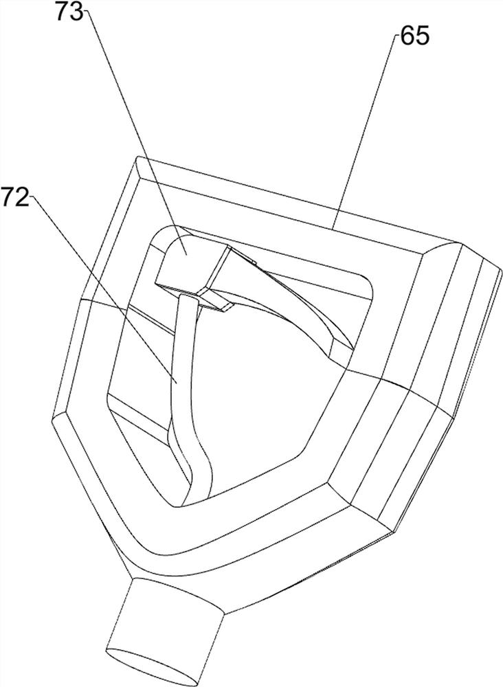
[0035] On the basis of Example 2, such as Figure 5As shown, a handle assembly 6 is also included, and the handle assembly 6 includes a second slide seat 60, a fixed plate 61, a swing bar 62, a positioning pin 64 and a rear handle 65, and the rear side of the guide frame 1 is connected with a second slide Seat 60, the top of the second sliding seat 60 is connected with a fixed plate 61, the fixed plate 61 is rotatably connected with a swing lever 62, and the fixed plate 61 is evenly spaced with multiple adjustment holes 63, and the adjustment hole 63 is slidably connected with a positioning The pin 64 and the swing rod 62 have a through hole, the positioning pin 64 can locate the swing rod 62, and the top of the swing rod 62 is connected with a rear handle 65.
[0036] When pulling the front handle 55 to move, you can grab the rear handle 65 with the other hand and apply pressure to the rear handle 65, so as to avoid excessive pressure on the front handle 55, which will cause ...
PUM
 Abstract
Description
Claims
Application Information
 - Generate Ideas
- Intellectual Property
- Life Sciences
- Materials
- Tech Scout
- Unparalleled Data Quality
- Higher Quality Content
- 60% Fewer Hallucinations
Browse by: Latest US Patents, China's latest patents, Technical Efficacy Thesaurus, Application Domain, Technology Topic, Popular Technical Reports.
© 2025 PatSnap. All rights reserved.Legal|Privacy policy|Modern Slavery Act Transparency Statement|Sitemap|About US| Contact US: help@patsnap.com