Post-construction steel bar bender

A bending device and steel bar technology, applied in the field of bending devices, can solve the problems of labor-intensive, low work efficiency, cumbersome operation process, etc., and achieve the effect of improving work efficiency, simple operation and saving manpower

Pending Publication Date: 2021-01-26
肖煌
View PDF6 Cites 1 Cited by
  • Summary
  • Abstract
  • Description
  • Claims
  • Application Information

AI Technical Summary

Problems solved by technology

[0006] In order to overcome the shortcomings of the above-mentioned method, such as cumbersome operation process, low work efficiency, and relatively labor-intensive operation, the technical problem to be solved by the present invention is to provide a steel bar that is easy to operate, can improve work efficiency, and saves manpower post-construction bender

Method used


Image

  • Post-construction steel bar bender
  • Post-construction steel bar bender
  • Post-construction steel bar bender

Examples


Embodiment 1

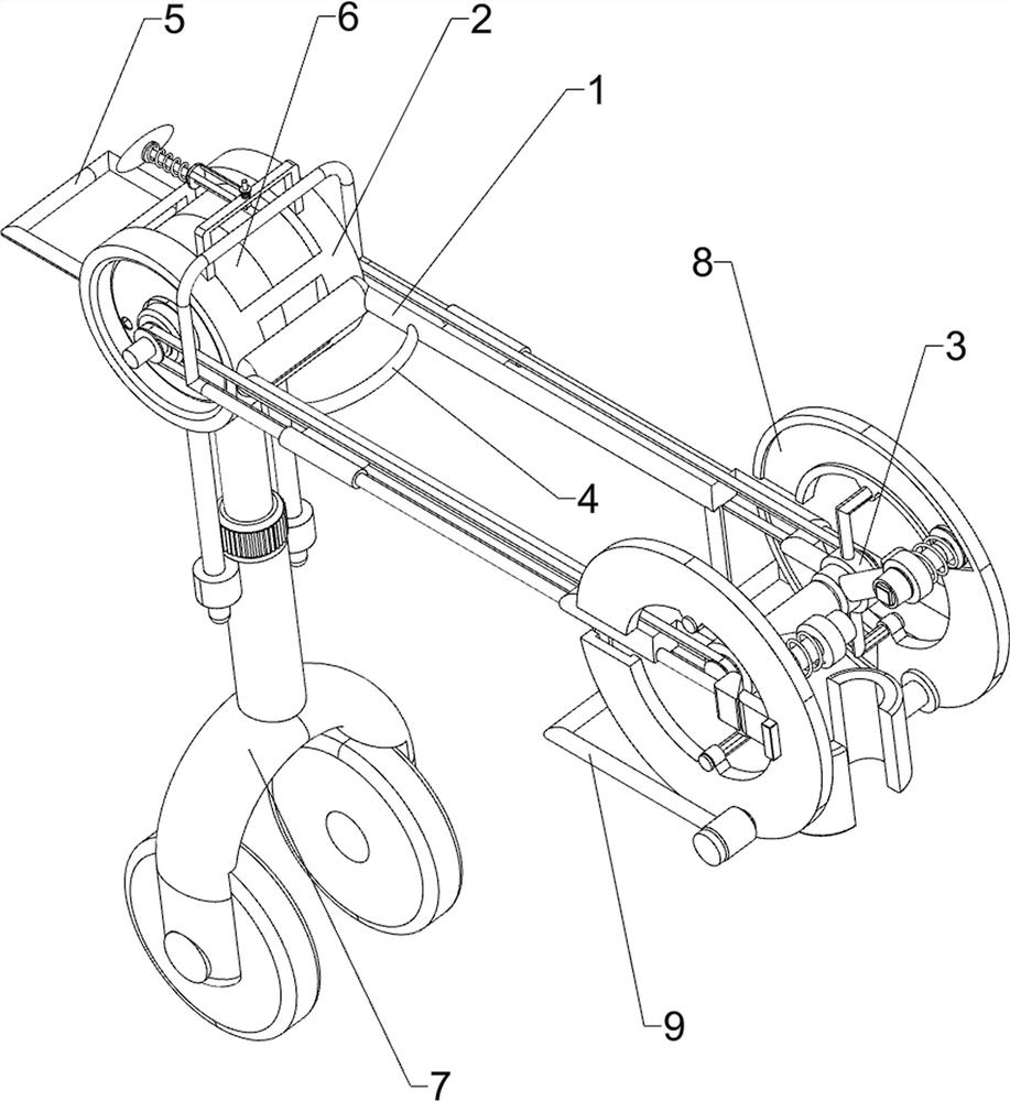
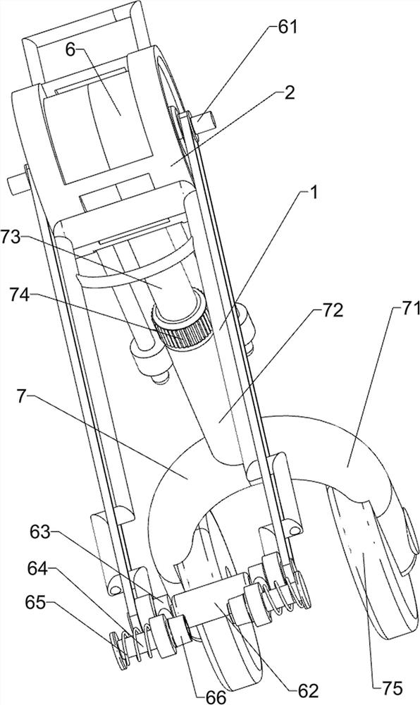
[0025] A post-construction bender for steel bars, such as figure 1 and figure 2 As shown, it includes a connecting frame 1, a mounting frame 2, a connecting bushing 3, a grip bar 4 and a pull rod 5, the left side of the connecting frame 1 is connected with the mounting frame 2, and the right side of the connecting frame 1 is connected with two connecting bushings 3, Two connecting bushes 3 are respectively connected to the front and rear sides of the connecting frame 1, the connecting frame 1 is connected with the handle bar 4, the installation frame 2 is connected with the pull rod 5, and also includes a bending assembly 6 and a moving assembly 7, the installation frame 2 A bending assembly 6 is provided between the connecting frame 1 and a moving assembly 7 is provided on the installation frame 2 .

[0026] The bending assembly 6 includes a biaxial motor 61, a connecting shaft roller 62, a rotating swing lever 63, a slide bar 64, a return spring 65 and a pulley 66, and a b...

Embodiment 2

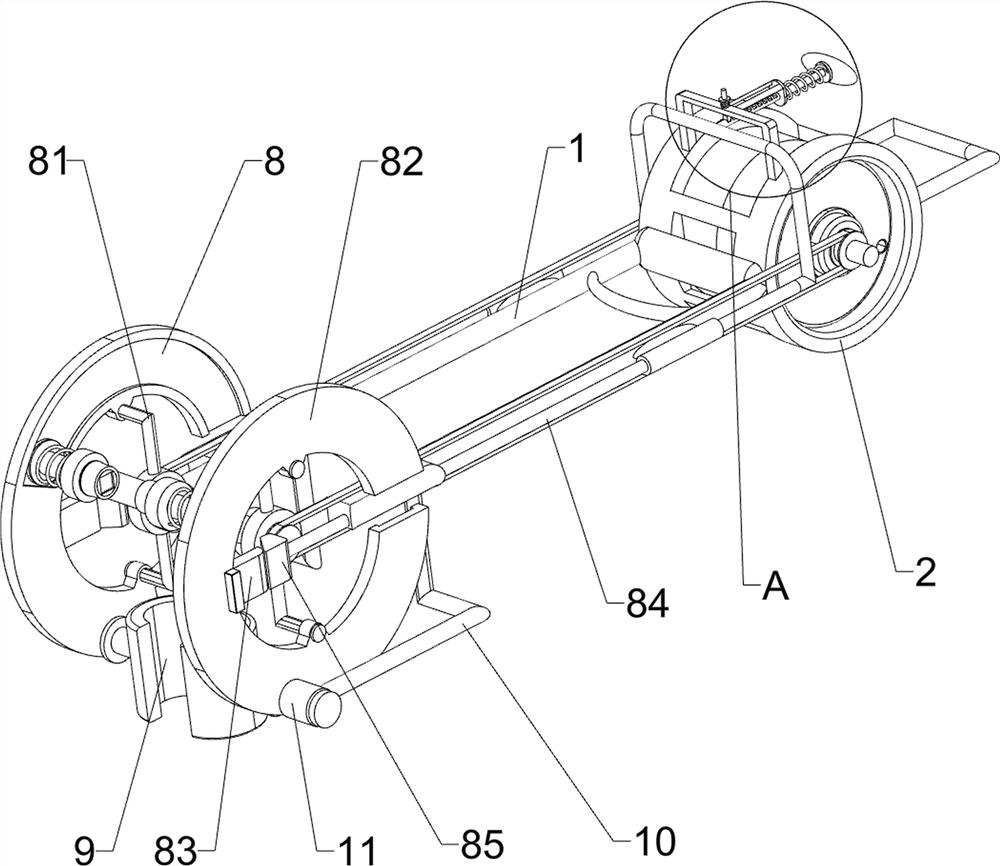
[0030] On the basis of Example 1, such as image 3 and Figure 4 As shown, a transmission assembly 8 is also included, and the transmission assembly 8 includes a clamping block 80, an L-shaped bar 81, a circular guide rail 82, a push block 83, a push rod 84, a wedge block 85, an n-shaped frame 86, a clamping rod 87, Connecting spring 88, vertical rod 89 and elastic member 90, L-shaped rods 81 are connected to the upper and lower sides of the connecting sleeve 3, and circular guide rails are slidingly connected between the two L-shaped rods 81 on the same connecting sleeve 3 82, the circular guide rail 82 is slidingly matched with the slide bar 64, the circular guide rail 82 is connected with a push block 83, the connecting frame 1 is slidably connected with a push rod 84, the front and rear sides of the push rod 84 are all connected with wedge blocks 85, wedge-shaped Block 85 cooperates with push block 83, and the top of installation frame 2 is connected with n-shaped frame 8...


PUM


Abstract

The invention relates to a bender, and especially relates to a post-construction steel bar bender. The technical problem to be solved by the invention is how to design the post-construction steel barbender which is simple to operate, and capable of increasing the working efficiency and saving the manpower. In order to solve the technical problem, the invention provides a post-construction steel bar bender. The post-construction steel bar bender comprises a connecting frame, connecting shaft sleeves, a holding rod, a pulling rod, a bending assembly and a moving assembly, wherein an installation case is connected to one side of the connecting frame; two connecting shaft sleeves are arranged, and connected to the other side of the connecting frame separately; the holding rod is connected tothe connecting frame; the pulling rod is connected to the installation case; the bending assembly is arranged between the installation case and the connecting frame; and the moving assembly is arranged on the installation case. The post-construction steel bar bender has the following beneficial effects: the bending assembly and the moving assembly cooperatively operate to bend steel bars, and therefore the effect of bending the steel bars is achieved.

Description

technical field [0001] The invention relates to a bender, in particular to a bender after steel bar construction. Background technique [0002] Steel bars are used for reinforced concrete and prestressed reinforced concrete. Most of the cross-sections of steel bars are circular, and some are square with rounded corners. The types of steel bars are divided into smooth round steel bars, ribbed steel bars, and twisted steel bars. After the reinforcement is laid, it is usually necessary to bend the reinforcement, bend the reinforcement into a specific angle, and then bind the reinforcement for construction. [0003] At present, the way to bend the steel bar is usually to manually use the fixing device to clamp the part of the steel bar that needs to be bent, and then the user will operate the bending equipment to squeeze the steel bar to make it bend along the part that needs to be bent. The operation process of the above method is relatively cumbersome, the work efficiency is...

Claims


Application Information

Patent Timeline
Patent Type & Authority Applications(China)
IPC IPC(8): B21F1/00
CPCB21F1/004
Inventor 肖煌
Owner 肖煌
Why Eureka
Try Eureka