Rotary mechanical arm of hydraulic manipulator

A technology of rotating machinery and manipulators, applied in the field of manipulators, can solve the problems of high maintenance technical requirements, limited range of activities, and increased purchase costs, and achieve the effect of low maintenance technical requirements, enhanced application scope, and simple and reasonable structure

Pending Publication Date: 2020-12-01
四川朗迪新材料有限公司
View PDF8 Cites 0 Cited by
  • Summary
  • Abstract
  • Description
  • Claims
  • Application Information

AI Technical Summary

Problems solved by technology

[0003] The mechanical arms currently on the market have disadvantages such as poor structural adjustment flexibility, complex structure, limited rotation angle, limited range of motion, and general work efficiency. The technical requirements for maintenance are relatively high, and the purchase cost increases due to its high price. If we can invent a mechanical arm with a simple structure, easy maintenance and manufacturing, and can achieve the purpose of use, it will undoubtedly be welcomed by the public. For this reason, we propose a hydraulic Rotating robotic arm for manipulators to meet demand

Method used


Image

  • Rotary mechanical arm of hydraulic manipulator
  • Rotary mechanical arm of hydraulic manipulator
  • Rotary mechanical arm of hydraulic manipulator

Examples


Embodiment Construction

[0026] In order to enable those skilled in the art to better understand the present invention, the technical solution of the present invention will be further described below in conjunction with the accompanying drawings and embodiments.

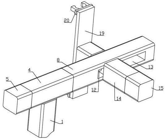
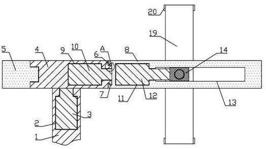
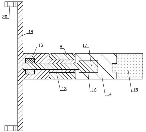
[0027] Such as figure 1 , figure 2 , image 3 , Figure 4 As shown, a rotary mechanical arm of a hydraulic manipulator of the present invention includes a main arm 1, a first mounting groove 2 is arranged in the main arm 1, a first rotating motor 3 is installed in the first mounting groove 2, and a first rotating motor 3 is installed in the first mounting groove 2. The output end of the motor 3 is connected with a first support arm 4, one end of the first support arm 4 is threadedly connected with a first counterweight 5, and the other end is integrally connected with a T-shaped cylinder 6, and the T-shaped cylinder 6 is matched with a first bearing 7, T The font cylinder 6 is rotated and matched with a second arm 8, the first arm 4 is p...


PUM


Abstract

The invention discloses a rotary mechanical arm of a hydraulic manipulator. A main arm is included, a first mounting groove and a first rotating motor are arranged in the main arm; the output end of the first rotating motor is connected with a first support arm; one end of the first supporting arm is in threaded connection with a first balancing weight, and the other end of the first supporting arm is integrally connected with a T-shaped cylinder; the T-shaped cylinder is in fit with a first bearing; the T-shaped cylinder is in rotational fit with a second support arm; a second mounting grooveand a second rotating motor are arranged in the first support arm; the output end of the second rotating motor is connected with the second support arm; a third mounting groove and a telescopic cylinder are arranged in the second support arm; the second support arm is provided with a rectangular sliding chute opening; the rectangular sliding chute opening is in sliding fit with a third support arm; one end of the third support arm is in threaded connection with a second balancing weight; a fourth mounting groove, a third rotating motor and a second bearing are arranged in the third support arm; the output end of the third rotating motor is connected with a transverse plate; and mechanical fingers are mounted on the transverse plate.

Description

technical field [0001] The invention belongs to the field of manipulators, and in particular relates to a rotating mechanical arm of a hydraulic manipulator. Background technique [0002] With the development and progress of science and technology, people's requirements for things have changed from the old thinking that can be used to become quite delicate and demanding. Only the idea of ​​continuous improvement or innovation will produce new forms to increase the added value of products. , in order to survive under the test of fierce market competition. Due to its unique operational flexibility, the robotic arm has been widely used in industrial assembly, safety and explosion-proof fields. [0003] The mechanical arms currently on the market have disadvantages such as poor structural adjustment flexibility, complex structure, limited rotation angle, limited range of motion, and general work efficiency. The technical requirements for maintenance are relatively high, and th...

Claims


Application Information

Patent Timeline
Patent Type & Authority Applications(China)
IPC IPC(8): B25J9/12B25J9/14
CPCB25J9/126B25J9/144
Inventor 朱以江陈海波高文铭
Owner 四川朗迪新材料有限公司
Why Eureka
Try Eureka