Bar speed measuring roller device

A speed-measuring roll and bar technology, which is applied in the field of bar rolling, can solve the problem of low measurement accuracy of the speed-measuring device, and achieve the effects of improving packaging efficiency and storage quality, light weight, and accurate and reliable speed measurement

Pending Publication Date: 2020-12-01
BAOTOU IRON & STEEL GRP
View PDF0 Cites 0 Cited by
  • Summary
  • Abstract
  • Description
  • Claims
  • Application Information

AI Technical Summary

Problems solved by technology

[0004] In view of the above-mentioned defects of the prior art, in order to solve the problem of low measurement accuracy of the existing speed measuring device, the present invention provides a speed measuring roller device, which has a large speed measuring range and high detection accuracy, is easy to detect and adjust, and can real-time Feedback to the control system to realize the control of the speed and position of the measured rolling piece

Method used


Image

  • Bar speed measuring roller device
  • Bar speed measuring roller device

Examples


Embodiment Construction

[0022] The following describes the embodiments of the present invention with reference to the accompanying drawings, so as to make the technical content clearer and easier to understand. The present invention can be embodied in many different forms of embodiments, and the protection scope of the present invention is not limited to the embodiments mentioned herein.

[0023] In the drawings, components with the same structure are denoted by the same numerals, and components with similar structures or functions are denoted by similar numerals. The size and thickness of each component shown in the drawings are shown arbitrarily, and the present invention does not limit the size and thickness of each component. In order to make the illustration clearer, the thickness of parts is appropriately exaggerated in some places in the drawings.

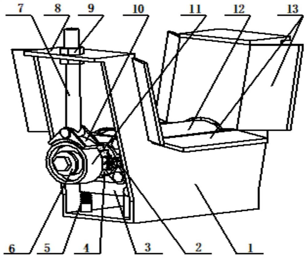
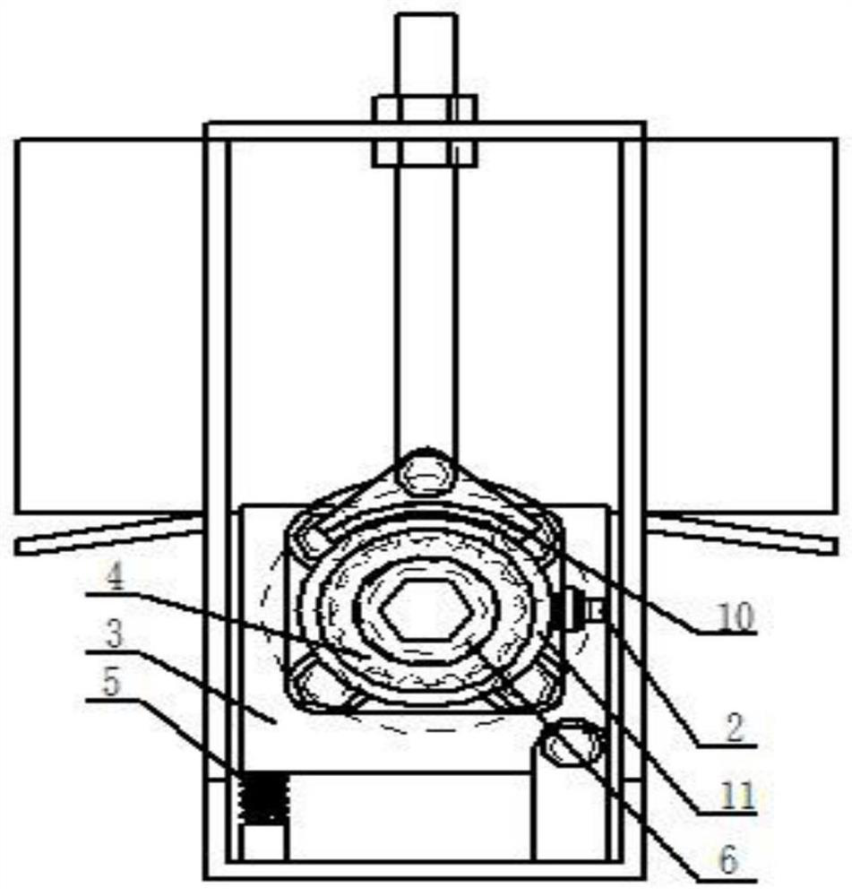
[0024] Such as figure 1 , 2 As shown, the bar material speed measuring roller device of the present invention includes a fixed base 1, a counte...


PUM


Abstract

The invention discloses a bar speed measuring roller device which comprises a fixed base, a swing bearing seat, a speed measuring roller, an elastic element, a counting gear, a band-type brake wheel,a band-type brake pressing seat, a lead screw and a counter. The speed measuring roller device is provided and is large in speed measurement range, high in detection precision, easy to detect and adjust, accurate and reliable in speed measurement, easy and convenient to install and adjust, capable of conducting detection in real time, low in accident rate, not high in requirement for the working condition environment, low in cost and capable of greatly improving the working efficiency.

Description

technical field [0001] The invention belongs to the technical field of bar rolling, and in particular relates to a speed-measuring roller device for packing and positioning finished bar products. Background technique [0002] At present, non-contact sensor detection is mostly used in the steel rolling production line, and the speed measurement function is realized by setting a pair of proximity switches or grating sensors. First determine the distance between the two sensors, and then calculate the average speed of the rolling piece by detecting the time passing through the two points. Due to the installation error and response time lag of the sensor, the measurement speed error is large; in addition, the sensor needs to adjust the distance between the two detection points according to the length of the rolled piece, so that the speed and position of the rolled piece cannot be controlled in real time; The time of measurement and adjustment has a great impact on the working ...

Claims


Application Information

Patent Timeline
IPC IPC(8): B21B38/00B21B37/00
CPCB21B38/00B21B37/00B21B37/005
Inventor 石振中
Owner BAOTOU IRON & STEEL GRP
Why Eureka
Try Eureka