Arrangement for a steam turbine

A steam turbine and component technology, applied to engine components, mechanical equipment, machines/engines, etc., can solve problems such as instability, rotor vibration, and periodic disturbance of pipelines

Active Publication Date: 2020-11-27
SIEMWNS ENERGY GLOBAL GMBH & CO KG
View PDF4 Cites 0 Cited by
  • Summary
  • Abstract
  • Description
  • Claims
  • Application Information

AI Technical Summary

Problems solved by technology

The flow field in the area assigned to the two ducts may be of an apparently unstable nature, which may induce periodic perturbations in the two ducts downstream, which may lead to undesired rotor vibrations

Method used


Image

  • Arrangement for a steam turbine
  • Arrangement for a steam turbine

Examples


Embodiment Construction

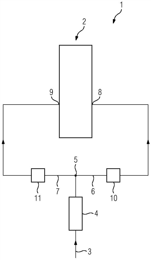
[0019] figure 1 An assembly 1 comprising a steam turbine 2 is shown. The steam turbine 2 has an outer casing (not shown in detail), an inner casing and a rotor. The steam generated in the steam generator flows into the steam turbine 2 via a live steam line 12 . A regulating valve 13 and a quick closing valve 14 are respectively arranged in the live steam line 12 . The steam flows into the live steam region 15 in the steam turbine. Here, the thermal energy of the steam is converted into mechanical rotational energy of the rotor. The additional steam mass flow flows through the additional steam valve 4 via the additional steam line 3 . After the additional steam valve, the steam flows to the splitter 5. The steam is split at the flow divider 5 and flows into the first auxiliary steam line 6 and the second auxiliary steam line 7 . In this case, the first additional steam line 6 opens into a first additional inflow area 8 which opens into a flow channel which is not shown in...


PUM


Abstract

The invention relates to an arrangement comprising a steam turbine (2) and two auxiliary steam lines to the steam turbine (2), wherein in each steam supply line there is arranged a diaphragm (10, 11)for the purpose of minimizing undesirable rotor vibrations.

Description

technical field [0001] The invention relates to an assembly comprising a steam turbine, a steam supply line fluidly connected to an inflow region of the steam turbine, and a steam valve arranged in the steam supply line, wherein the inflow region is fluidly connected to a flow channel, further comprising An additional steam line fluidly connected to an additional inflow region of the steam turbine, an additional steam valve arranged in the additional steam line, wherein the additional inflow region is arranged downstream of the flow channel. Background technique [0002] A steam turbine generally comprises a plurality of turbine sections, for example divided into a high-pressure turbine section, an intermediate-pressure turbine section and a low-pressure turbine section. Some steam turbine implementations include multiple turbine sections and have a common shaft. The length of the shaft is relatively long here. Generate live steam in the steam generator. The live steam re...

Claims


Application Information

Patent Timeline
Patent Type & Authority Applications(China)
IPC IPC(8): F01D17/14F01D25/04
CPCF01D17/141F01D17/145F01D25/04F05D2220/31
Inventor S·黑克尔L·霍迈尔N·皮珀R·昆科茨M·韦克松
Owner SIEMWNS ENERGY GLOBAL GMBH & CO KG
Why Eureka
Try Eureka