
Method and system for controlling movement in immersive virtual reality

A virtual reality, immersive technology, applied in mechanical mode conversion, input/output process of data processing, input/output of user/computer interaction, etc. The effect of cost, lightness of equipment, wide application and commercial value

Pending Publication Date: 2020-11-27
李欢
View PDF0 Cites 4 Cited by
  • Summary
  • Abstract
  • Description
  • Claims
  • Application Information

AI Technical Summary

Problems solved by technology

[0007] The purpose of the present invention is to provide a method and system for controlling movement in immersive virtual reality, so as to solve the problems of high cost and unnatural user movements in the existing movement control technology based on body movements

Method used

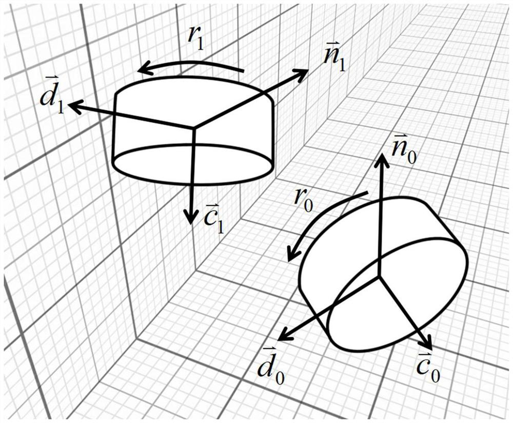
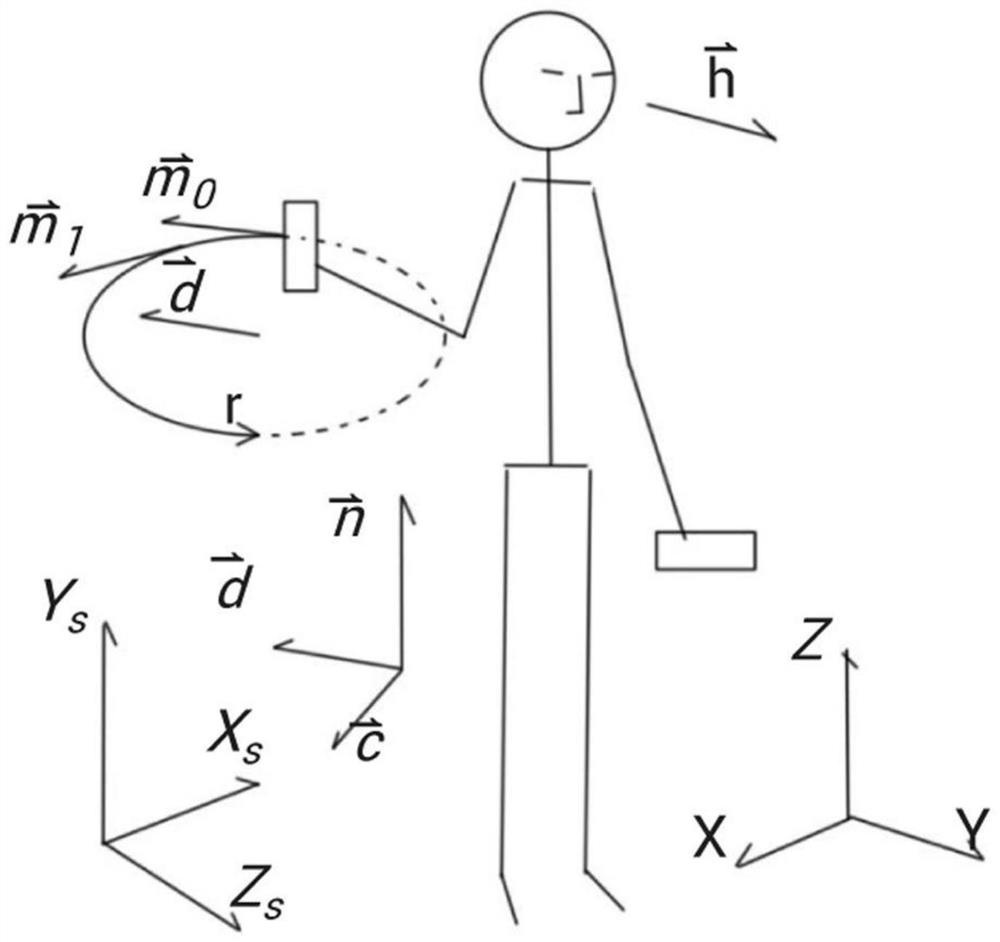
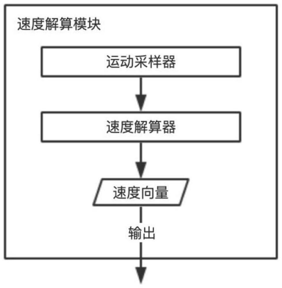

Image

  • Method and system for controlling movement in immersive virtual reality
  • Method and system for controlling movement in immersive virtual reality
  • Method and system for controlling movement in immersive virtual reality

Examples


Embodiment 1

[0065] The user is equipped with a mainstream immersive virtual reality device. In this embodiment, only the six-degree-of-freedom handle held by both hands is related to the method for controlling movement described in the present invention, and the helmet has nothing to do with the present invention. In this embodiment, the system flow chart is as follows Figure 5 As shown, the initialization module is specifically to set the two six-degree-of-freedom handles to the working state.

[0066] The speed synthesis module in this embodiment is specifically Figure 6 shown, with Figure 4 The difference is: Figure 6 The speed calculation module is specifically a left handle speed calculation module and a right handle speed calculation module. Figure 6 The speed calculation module of the left handle or the speed calculation module of the right handle in Figure 7 describe. Figure 7 and image 3 The difference is that: Figure 7 The motion sampler in is specifically a hand...

Embodiment 2

[0068] The user is equipped with an Oculus Quest helmet among mainstream immersive virtual reality devices. Since the helmet supports bare-hand recognition, the user only needs to wear the helmet to apply the method for controlling movement in the present invention. In this embodiment, the system flow chart is still as follows Figure 5 As shown, the initialization module specifically sets the helmet to the working state of bare-hand recognition.

[0069] The speed synthesis module in this embodiment is specifically Figure 8 shown, with Figure 4 The difference is: Figure 8 The speed calculation module in is specifically a left palm speed calculation module and a right palm speed calculation module. Figure 8 The left palm velocity calculation module or the right palm velocity calculation module in Figure 9 describe. Figure 9 and image 3 The difference is that: Figure 9 The motion sampler in is specifically a palm motion sampler, which can sample the motion data o...


PUM


Abstract

The invention provides a method and a system for controlling movement in immersive virtual reality. According to the method and the system, a user performs curvilinear motion in one or more limb partsin the expected moving direction, the expected moving speed is expressed at the intense degrees of the moving speed, amplitude and the like, and the system converts the limb actions into the moving direction and speed of the user in the virtual environment, so that the aim of controlling the role to move is fulfilled. According to the invention, only a relatively small real space is needed; onlya mainstream immersive virtual reality product needs to be purchased and worn, equipment is light, extra equipment cost is not needed, and no constraint is caused to the body; the moving direction andthe watching direction are independent, and the moving direction is not affected when a user observes the surroundings; a user can control movement by using a single, simple and convenient action; and limb movement and movement speed are consistent in perception, and motion sickness is relieved. The method can meet the requirements at the same time, and therefore the method has wide application and commercial value.

Description

technical field [0001] The invention relates to the technical field of immersive virtual reality, in particular to a method and system for controlling movement in immersive virtual reality. Background technique [0002] In the field of immersive virtual reality, how to effectively suppress motion sickness by controlling movement is an important direction of academic research and product development. Research and practice have shown that, compared with traditional keyboard and mouse button methods, controlling movement through body movements can effectively relieve motion sickness. Obtaining a perceptually consistent movement speed that matches body movements can further alleviate motion sickness, which is one of the evaluation indicators for movement control methods. The separation of movement direction and gaze direction can give users a more natural movement experience, which is also one of the evaluation indicators of movement control methods. [0003] At present, mobil...

Claims


Application Information

Patent Timeline
Patent Type & Authority Applications(China)
IPC IPC(8): G06F3/01
CPCG06F3/011G06F2203/012
Inventor 李欢刘博宁
Owner 李欢
Learn More