Tamping equipment

A kind of equipment and technology of cyclone separation device, which is applied in the field of compaction equipment of cyclone separation device, can solve the problems of reducing the service life of the filter element, increasing the cleaning frequency of the filter element, etc., and achieve the effects of avoiding filter element clogging, simple structure and high separation efficiency

Pending Publication Date: 2020-11-27
B D X MACHINERY LTD
View PDF0 Cites 0 Cited by
  • Summary
  • Abstract
  • Description
  • Claims
  • Application Information

AI Technical Summary

Problems solved by technology

Greatly increase the cleaning frequency of the filter element and reduce the service life of the filter element

Method used


Image

  • Tamping equipment
  • Tamping equipment
  • Tamping equipment

Examples


Embodiment Construction

[0030] The following description is merely exemplary in nature and is not intended to limit the disclosure and its application or uses.

[0031] Example embodiments are provided so that this disclosure will be thorough, and will fully convey the scope to those who are skilled in the art. Numerous specific details are set forth, such as examples of specific components, devices, and methods, in order to provide a thorough understanding of embodiments of the present disclosure. It will be apparent to those skilled in the art that specific details need not be employed, that example embodiments may be embodied in many different forms and that neither should be construed to limit the scope of the disclosure. In some example embodiments, well-known methods, well-known device structures, and well-known technologies are not described in detail.

[0032] When an element or layer is referred to as being "on," "bonded to," "connected to," or "coupled to" another element or layer, the ele...


PUM


Abstract

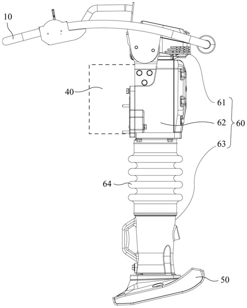
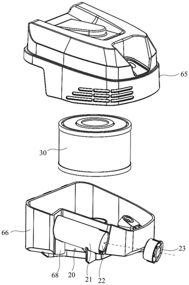
The invention relates to tamping equipment comprising an internal combustion engine as a power source of the tamping equipment. The tamping equipment further comprises a cyclone separation device forpurifying inlet air of the internal combustion engine. The cyclone separation device comprises a cylindrical peripheral wall, an inlet, a flow guide fan arranged in the inlet, a transverse wall arranged transversely to the peripheral wall, an air outlet formed in the center of the transverse wall, and a particulate matter outlet formed in the peripheral wall and adjacent to the transverse wall. The problem that a filter element of the tamping equipment needs to be frequently replaced is solved.

Description

technical field [0001] The present invention relates to a compaction device, and more particularly to a compaction device with a cyclone separation device for pre-separation of particulate matter such as dust before the air enters the air filter device of the engine. Background technique [0002] This section provides background information related to the present disclosure which is not necessarily prior art. [0003] Tamping equipment usually works on sandy ground. During high-frequency compaction work, dust will fly up due to the continuous hammering of the ramming plate, and the dust and other particles will be much higher than the general working environment. The engine of ordinary tamping equipment comes with a random filter element as the main air filter device. Therefore, it is generally necessary to maintain the filter element every 20 hours to remove debris from the filter element, and to replace the filter element every 200 hours. Otherwise, the engine may have p...

Claims


Application Information

Patent Timeline
IPC IPC(8): F02M35/022
CPCF02M35/0223Y02A50/2351
Inventor 王冠伟
Owner B D X MACHINERY LTD
Why Eureka
Try Eureka