
Engine crankcase ventilation system and method

A technology of crankcase ventilation and ventilation method, which is applied in the direction of crankcase ventilation, engine components, machines/engines, etc., can solve the problems of rapid aging of engine oil and emulsification of engine oil, so as to reduce the aging speed of engine oil, improve the emulsification of engine oil, and reduce parts wear effect

Inactive Publication Date: 2020-11-27
KUNMING YUNNEI POWER +1
View PDF7 Cites 4 Cited by
  • Summary
  • Abstract
  • Description
  • Claims
  • Application Information

AI Technical Summary

Problems solved by technology

It can only realize the oil-gas separation of air leakage and the control of the crankcase pressure, but cannot solve the problems of rapid oil aging, freezing at the end of the breathing tube in winter low temperature environment, and oil emulsification on the oil filler cap and the oil-gas separator wall

Method used


Image

  • Engine crankcase ventilation system and method

Examples


Embodiment Construction

[0027] The following will clearly and completely describe the technical solutions in the embodiments in conjunction with the accompanying drawings in the embodiments of the present application. Obviously, the described embodiments are only a part of the embodiments of the present invention, rather than all the embodiments. Based on the embodiments, all other embodiments obtained by persons of ordinary skill in the art without creative efforts fall within the protection scope of the present invention.

[0028] Unless otherwise defined, the technical terms or scientific terms used in the embodiments of the present application shall have the usual meanings understood by those skilled in the art. "First", "second" and similar words used in this embodiment do not indicate any order, quantity or importance, but are only used to distinguish different components. "Comprising" or "comprising" and similar words mean that the elements or items appearing before the word include the elemen...


PUM


Abstract

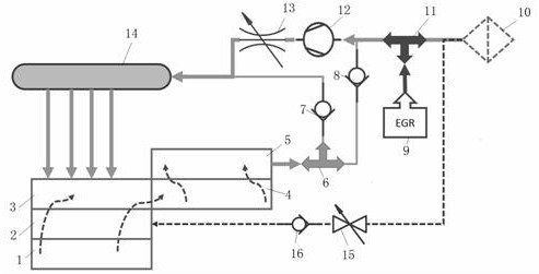
The invention relates to an engine crankcase ventilation system and method. The system comprises an engine crankcase, one end of a PCV valve communicates with an oil-gas separator, one end of the PCVvalve communicates with the air inlet end of an intake manifold through a first one-way valve, and one end of the PCV valve communicates with one output end of a supercharger and an EGR mixing valve through a second one-way valve, an EGR cooler communicates with the input end of the EGR mixing valve, the other output end of the EGR mixing valve communicates with an air filter, the other end of thesupercharger communicates with the air inlet end of the intake manifold, and the air outlet end of the intake manifold communicates with an engine cylinder cover. According to the system, an engine oil aging speed can be effectively reduced, engine oil emulsification risk of a valve chamber cover, an oil filling cover and the wall surface of the oil-gas separator can be reduced, and the problem of a failure of icing at the tail end of a breathing tube in winter can be solved.

Description

technical field [0001] The invention belongs to the field of engines, in particular to an engine crankcase ventilation system and method. Background technique [0002] When the engine is working, the high-pressure combustible mixture and burned gas in the combustion chamber will inevitably leak into the crankcase through the gap between the piston ring and the cylinder, resulting in air leakage. The main components of air leakage are burned exhaust gas, unburned fuel gas and water vapor generated by fuel combustion. The SO2 in the exhaust gas after combustion combines with water vapor to form sulfurous acid, and the sulfurous acid meets the oxygen in the air to form sulfuric acid. The appearance of these acidic substances accelerates the oxidation of the engine oil, which not only deteriorates the engine oil, but also corrodes the parts. If the leakage air is not released, the pressure in the crankcase will rise sharply, causing oil leakage from the front and rear oil seals...

Claims


Application Information

Patent Timeline
IPC IPC(8): F01M13/00F01M13/04F02M25/06F02M26/17F02M26/19
CPCF01M13/00F01M13/04F01M2013/0438F01M2013/0488F02M25/06F02M26/17F02M26/19
Inventor 易小峰张海丰李小侠季路芹王成苏煜森
Owner KUNMING YUNNEI POWER
Learn More