Quenching furnace for tubular parts

A technology for quenching furnaces and parts, applied in the field of quenching furnaces, can solve the problems of not including cleaning and drying of parts driven by the same power, increasing equipment space occupation and cost, and low reliability of sensors, so as to ensure timeliness and synchronization. , to avoid hot air scalding people, easy to maintain the effect

Active Publication Date: 2020-11-27
CHONGQING CHANGJIANG INDAL FURNACE MFG
View PDF7 Cites 2 Cited by
  • Summary
  • Abstract
  • Description
  • Claims
  • Application Information

AI Technical Summary

Problems solved by technology

[0003] The disadvantages of existing quenching furnaces for tubular parts are: 1. The existing quenching furnace drives the parts forward, cooling and drying through multiple power sources, which increases the cost and is not convenient to ensure the synchronization of the processing technology; 2. The existing quenching furnace drives the parts forward by setting multiple and independent power, which increases the space occupation and cost of the equipment, and is not convenient for the maintenance of the later parts; 3. The existing quenching furnace does not include the same power to drive the heat treatment In the previous parts cleaning and parts drying, impurities on the surface of the parts to be processed during heat treatment will affect the quality of heat treatment; 4. When the existing quenching furnace cools the heated parts, the hot gas generated is directly discharged into the air, wasting 5. The existing quenching furnace controls the clamping components to move forward through the sensor, and the reliability of the sensor is lower than that of the mechanical transmission clamping forward.

Method used


Image

  • Quenching furnace for tubular parts
  • Quenching furnace for tubular parts
  • Quenching furnace for tubular parts

Examples


Embodiment Construction

[0063] The present invention will be further described below in conjunction with drawings and embodiments.

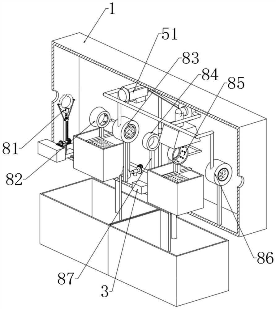
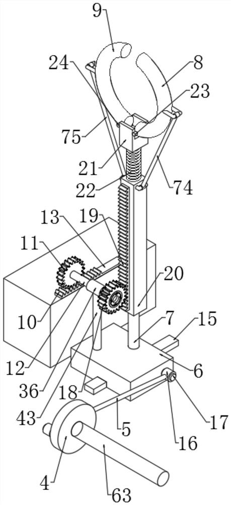
[0064] Such as Figure 1 to Figure 14 As shown, a quenching furnace for tubular parts includes a furnace body 1, the furnace body 1 is provided with a cavity, and the two opposite side walls of the furnace body 1 are provided with inlets and outlets for passing through the parts to be processed, and the furnace body 1 According to the process, there are clamping unit 81, cleaning unit 82, first drying unit 83, heating unit 84, cooling unit 85, and second drying unit 86. The entrance of the furnace body 1 corresponds to the clamping unit 81, and the second drying unit 86 corresponds to the outlet of the furnace body 1; the power unit includes a motor 51, and the motor 51 provides power for the clamping unit 81, the cleaning unit 82, the first drying unit 83, the cooling unit 85, and the second drying unit 86; The heating unit 84 is electrically connected to the power su...


PUM


Abstract

The invention discloses a quenching furnace for tubular parts. The quenching furnace comprises a furnace body, wherein a cavity is formed in the furnace body, the two opposite side walls of the furnace body are provided with an inlet and an outlet which are used for allowing the part to be treated to penetrate through, a clamping unit, a cleaning unit, a first drying unit, a heating unit, a cooling unit and a second drying unit are sequentially arranged in the furnace body according to procedures, the furnace body inlet corresponds to the clamping unit, and the second drying unit corresponds to the furnace body outlet; a power unit comprises a motor, and the motor provides power for the clamping unit, the cleaning unit, the first drying unit, the cooling unit and the second drying unit atthe same time; the heating unit is electrically connected with a power supply; and the clamping unit can reciprocate in the moving direction of the part to be treated and complete the clamping and loosening functions of the part to be treated. According to the quenching furnace, a part is clamped by the clamping unit to move forwards, the part is subjected to cleaning, primary drying, heating, cooling and secondary drying, the tubular part is quenched and dried, and high practicability is achieved.

Description

technical field [0001] The invention relates to the field of heat treatment equipment, in particular to a quenching furnace for tubular parts. Background technique [0002] Quenching is a heat treatment process that heats steel above the critical temperature, holds it for a certain period of time, and then cools it at a rate greater than the critical cooling rate to obtain an unbalanced structure dominated by martensite, bainite or austenite. Induction hardening is a quenching method that uses electromagnetic induction to generate eddy currents in the workpiece to heat the workpiece, and then rapidly cools the heated workpiece. [0003] The disadvantages of existing quenching furnaces for tubular parts are: 1. The existing quenching furnace drives the parts forward, cooling and drying through multiple power sources, which increases the cost and is not convenient to ensure the synchronization of the processing technology; 2. The existing quenching furnace drives the parts fo...

Claims


Application Information

Patent Timeline
IPC IPC(8): C21D9/08C21D1/667
CPCC21D1/667C21D9/0018C21D9/0025C21D9/0062C21D9/085
Inventor 蒋波谢洪砖杨天虹谯中昂伍元祥
Owner CHONGQING CHANGJIANG INDAL FURNACE MFG
Why Eureka
Try Eureka