
Charging device

A charging device and charging pile technology, applied in charging stations, electric vehicle charging technology, electric vehicles, etc., can solve problems such as affecting the performance of charging piles and being easily damaged.

Active Publication Date: 2020-11-27
SHENZHEN POWER SUPPLY BUREAU
View PDF10 Cites 2 Cited by
  • Summary
  • Abstract
  • Description
  • Claims
  • Application Information

AI Technical Summary

Problems solved by technology

[0003] Based on this, it is necessary to provide a charging device for the technical problem that the charging pile in the prior art is easily damaged during use, thereby affecting the performance of the charging pile.

Method used


Image

  • Charging device
  • Charging device
  • Charging device

Examples


Embodiment 1

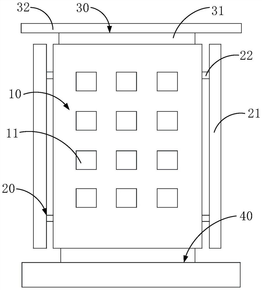
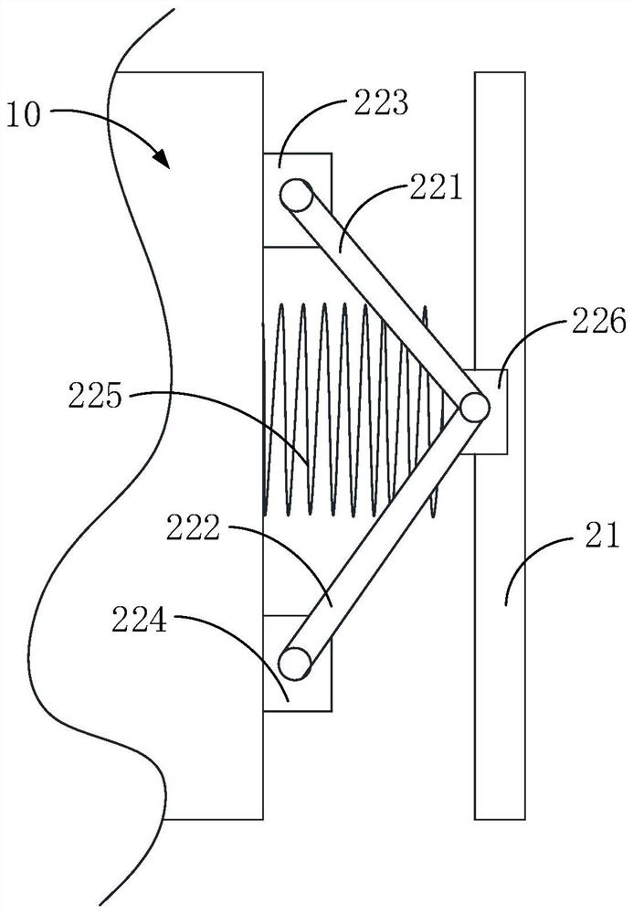
[0038] refer to figure 1 , figure 1 A simplified schematic diagram of the charging device in Embodiment 1 of the present invention is shown. The charging device provided in Embodiment 1 of the present invention includes a charging pile 10 , a first protection component 20 and a second protection component 30 . Wherein, the first protective part 20 is installed on the peripheral side of the charging pile 10, and the first protective part 20 can move closer and farther away from the side wall of the charging pile 10. The first protective part 20 has a plug hole, and the plug hole is convenient for charging. The charging plug 11 on the pile 10 protrudes to the outside of the first protection part 20; the second protection part 30 is covered on the top of the charging pile 10; the second protection part 30 is provided with a flow guide part, which is used for flow guide rainwater.

[0039]Specifically, a charging plug 11 is provided on the side wall of the charging pile 10, and ...

Embodiment 2

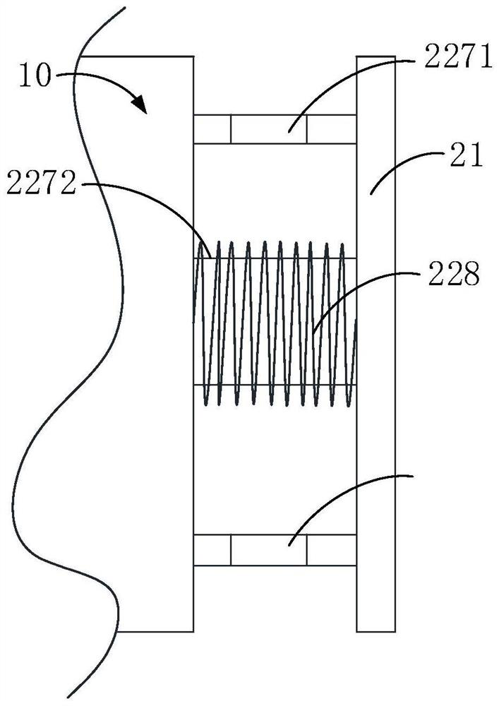
[0059] refer to image 3 , image 3 It shows a partial schematic view of the first protective component installed on the charging pile in the charging device provided by the second embodiment of the present invention. The charging device provided in the second embodiment is different from the charging device in the first embodiment in that the adjustment mechanism includes a telescopic rod; one end of the telescopic rod is connected to the charging pile 10, and the other end of the telescopic rod is connected to the buffer pad twenty one.

[0060] Specifically, the telescopic rod includes a plurality of rod bodies that are sheathed in sequence, and any two adjacent rod bodies are sheathed between. Taking three rods as an example, the three rods are respectively the first rod, the second rod and the third rod, and the first rod, the second rod and the third rod are sequentially connected end to end. That is: the second end of the first rod is sleeved on the first end of the ...


PUM


Abstract

The invention relates to a charging device. The charging device comprises a charging pile, a first protection part, and a second protection part, wherein the first protection part is installed on a peripheral side of the charging pile, and the first protection part can move close to or away from the side wall of the charging pile; the first protection part is provided with a plug hole, and the plug hole facilitates a charging plug on the charging pile to extend to the outer side of the first protection part; the second protection part covers the top of the charging pile; and the second protection part is provided with a flow guide part used for guiding rainwater. According to the charging device provided by the invention, the first protection part and the second protection part are matchedfor use, and a protective cover is additionally arranged on the outer side of the charging pile so that collision from the outside is buffered, rain and sun can be shielded, the protection performance of the charging pile is improved, a probability that the charging pile is prone to damage is reduced, the charging pile is ensured to have good use performance, and a service life is prolonged.

Description

technical field [0001] The invention relates to the technical field of photovoltaic charging, in particular to a charging device. Background technique [0002] The input end of the charging pile is directly connected to the AC power grid, and the output end is equipped with a charging plug for charging the electric vehicle. Usually, charging piles are set up near parking lots or stations. Considering the sustainability and environmental protection of charging piles, charging piles are generally connected with self-generated photovoltaic power generation devices. However, in actual use, the charging pile needs to be exposed to the outside in order to connect to the electric vehicle, and the electric vehicle needs to be parked near the charging pile when charging. Therefore, sometimes due to the driver's misoperation or irregular parking, it will collide with the charging pile, and then damage the charging pile. At the same time, it is precisely because the charging pile is ...

Claims


Application Information

Patent Timeline
IPC IPC(8): B60L53/31B60L53/30B60L53/16
CPCB60L53/31B60L53/30B60L53/16Y02T10/70Y02T10/7072Y02T90/12Y02T90/14
Inventor 李腾腾杜进桥田杰
Owner SHENZHEN POWER SUPPLY BUREAU
Learn More