Medicinal material screening vibration motor
A technology of vibrating motors and medicinal materials. It is applied in the direction of filters, electromechanical devices, electrical components, etc. It can solve problems such as temperature rise, leakage safety risks, and affecting the use of internal circuits. It achieves simple installation and disassembly, and prevents damage to internal parts and circuits. , Reduce maintenance difficulty and work intensity
- Summary
- Abstract
- Description
- Claims
- Application Information
AI Technical Summary
Problems solved by technology
Method used
Image
Examples
Embodiment 1
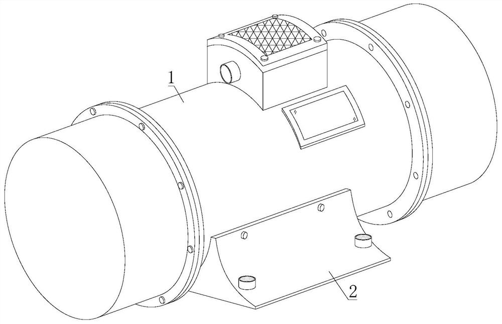
[0030] refer to figure 1 , 2, 3, 4 and 6, the vibrating motor for screening medicinal materials, including a main body mechanism 1 and a fixed seat 2, the upper end of the fixed seat 2 is provided with a main body mechanism 1, and the main body mechanism 1 includes a main cylinder body 11, a connecting flange 12, and an end cover 13 , stator 14, rotor 15, brake mechanism 16, eccentric mechanism 17 and protective wall 18, the two ends of main cylinder 11 are fixedly installed with connecting flange 12, and one end of connecting flange 12 is provided with end cover 13, and main cylinder 11 is provided with a stator 14 and a rotor 15, both ends of the rotor 15 are provided with an eccentric mechanism 17, the eccentric mechanism 17 is arranged inside the end cover 13, and the outer surface of the rotor 15 is provided with a braking mechanism 16 and a protective wall 18 It is arranged on the inner wall of the main cylinder 11 , and the lower end of the main cylinder 11 is provided...
Embodiment 2
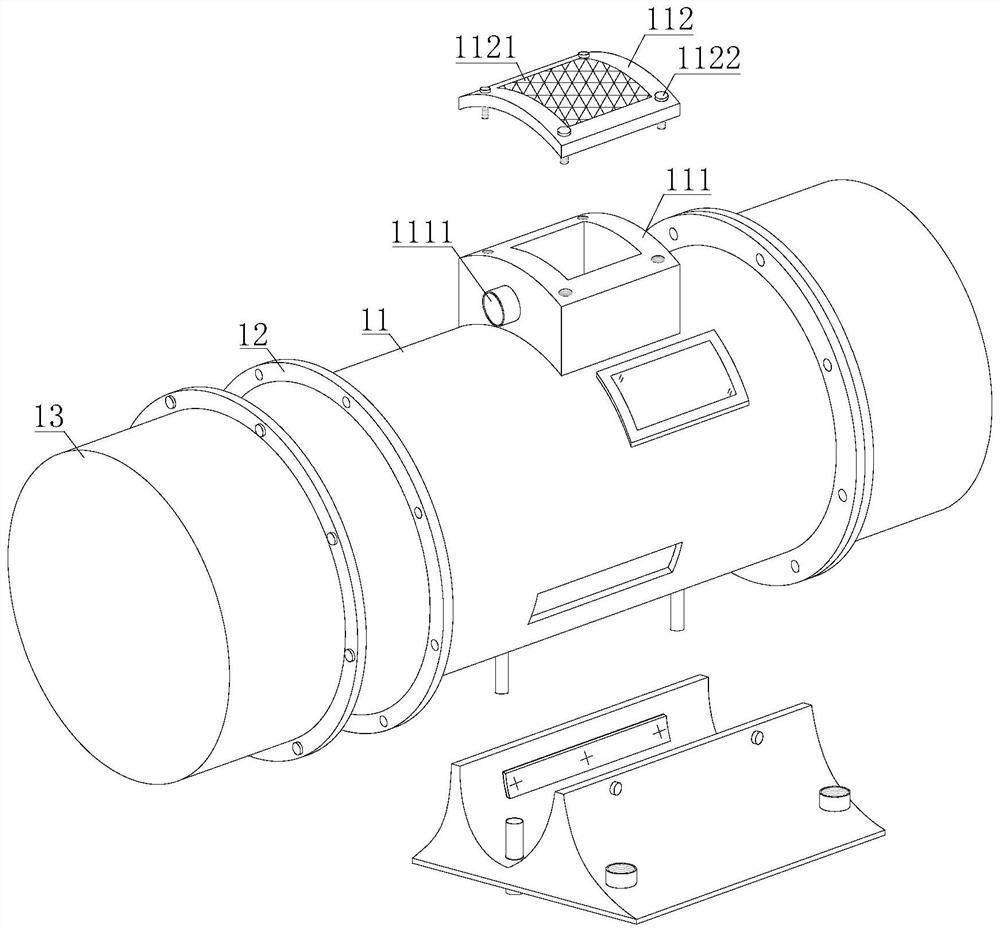
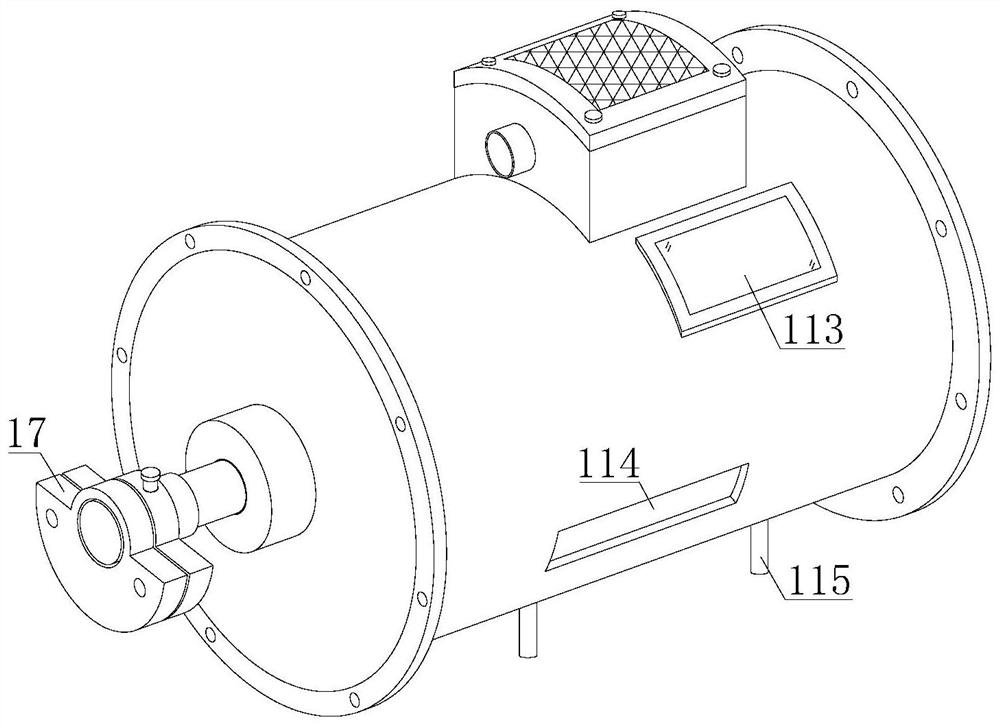
[0032] refer to image 3 and 4 , the fixed seat 2 includes a U-shaped groove 21, a threaded fixing hole 22 and an adjusting bolt 23, the upper surface of the fixed seat 2 is provided with a U-shaped groove 21, and the outer surface of the fixed seat 2 is provided with a threaded fixing hole 22 and an adjusting bolt 23, The fixing seat 2 is connected with the outside world through the threaded fixing hole 22. The main cylinder body 11 includes a wiring groove 111, a heat dissipation cover 112, a control panel 113, a mounting groove 114 and a conductive rod 115. The upper surface of the main cylinder body 11 is fixedly equipped with a wiring groove 111, the upper end of the wiring groove 111 is provided with a heat dissipation cover 112, the outer surface of the main cylinder 11 is fixedly installed with a control panel 113, the lower bottom surface of the main cylinder 11 is provided with a mounting groove 114, and the lower end of the main cylinder 11 is fixedly installed with...
Embodiment 3
[0034] refer to figure 2 and 5 , the outer surface of the wiring groove 111 is provided with a lead tube 1111, the stator 14 is electrically connected to the external power supply through the wiring groove 111, and the outer surface of the heat dissipation cover 112 is provided with a heat dissipation grid 1121 and a threaded pin 1122, and the heat dissipation cover 112 is passed through the threaded pin. 1122 is movably connected with the wiring groove 111. The eccentric mechanism 17 includes an eccentric block A171, an eccentric block B172, a sleeve shaft 173, a connecting hole 174 and a connecting pin 175. Both the eccentric block A171 and the eccentric block B172 are arranged on the outer surface of the sleeve shaft 173. The eccentric block A171 is arranged on the outside of the eccentric block B172, and the outer surfaces of the eccentric block A171 and the eccentric block B172 are provided with connecting holes 174, and the inside of the connecting hole 174 is provided ...
PUM
 Abstract
Description
Claims
Application Information
 - R&D
- Intellectual Property
- Life Sciences
- Materials
- Tech Scout
- Unparalleled Data Quality
- Higher Quality Content
- 60% Fewer Hallucinations
Browse by: Latest US Patents, China's latest patents, Technical Efficacy Thesaurus, Application Domain, Technology Topic, Popular Technical Reports.
© 2025 PatSnap. All rights reserved.Legal|Privacy policy|Modern Slavery Act Transparency Statement|Sitemap|About US| Contact US: help@patsnap.com


