
Pneumatic tire

A technology of pneumatic tires and tires, which is applied to heavy tires, tire parts, tire treads/tread patterns, etc., can solve problems such as uneven wear, achieve good balance, improve traction performance on snow, and avoid excessive reduction in rigidity Effect

Active Publication Date: 2020-11-24
THE YOKOHAMA RUBBER CO LTD
View PDF11 Cites 0 Cited by
  • Summary
  • Abstract
  • Description
  • Claims
  • Application Information

AI Technical Summary

Problems solved by technology

Moreover, tires such as the above, in addition to the fact that the tread pattern is the base tone of the block, have a high frequency of braking and driving in relation to the conditions of use, and in addition, the frequency of driving in sharp turns is also high, so there is a tendency for uneven wear to occur. Tendency, it is also required to maintain or improve the uneven wear resistance

Method used


Image

  • Pneumatic tire
  • Pneumatic tire
  • Pneumatic tire

Examples


Embodiment

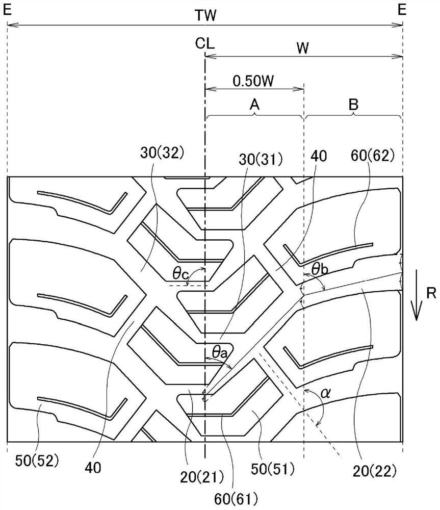
[0056] Made conventional example 1, 22 kinds of pneumatic tires of embodiment 1~21, the tire size of these pneumatic tires is 315 / 80R22.5, has figure 1 The illustrated basic structure sets the following contents as shown in Tables 1 and 2: the tread pattern as the base tone, the average angle θa of the second groove portion of the lug groove in the inner region A with respect to the tire circumferential direction, and the outer region A. In B, the average angle θb of the second groove portion of the lug groove relative to the tire circumferential direction, the angle θc of the first groove portion of the lug groove relative to the tire circumferential direction, the magnitude relationship between the average angle θa and θb, and whether it is shallow or not Groove, groove depth of shallow groove, shape of shallow groove, shape of central shallow groove, presence or absence of repetition of projected components projecting central shallow groove toward the tire equator (repetitio...


PUM


Abstract

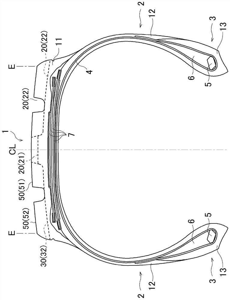
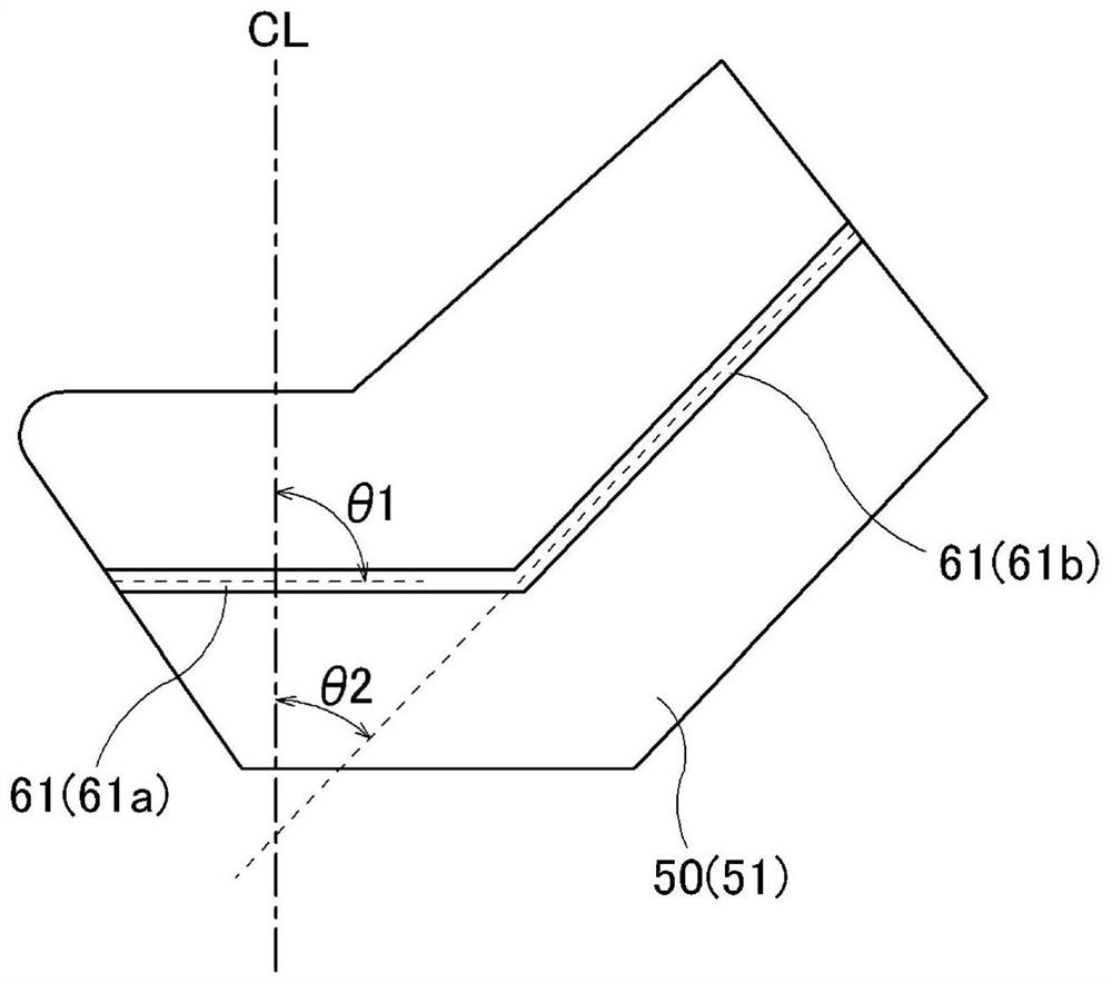
Provided is a pneumatic tire that allows improvement of snow traction performance while favorably maintaining performance in resistance to uneven wear and maintaining traveling performance on an unpaved road. Lug grooves (20, 30) are alternately arranged, the lug grooves (20, 30) comprising first groove portions (21, 31) intersecting with a tire center line CL and extending in the tire width direction and second groove portions (22, 32) respectively inclined, from ends of the first groove portions (21, 31), at acute angles in the tire circumferential direction relative to the first groove portions (21, 31) so as to extend to tread ends E on one side and the other side relative to the tire center line. The other ends of the first groove portions (21, 31) are in communication with the respective second groove portions (32, 22), of the lug grooves (30, 20), adjacent to each other in the tire circumferential direction. The first groove portions (21, 31) are arranged on a stepping-in side relative to the ends of the tread end E sides of the lug grooves (20, 30). The second groove portions (22, 32) are curved or bent such that the average angle theta in an inner side region A of the second groove portions (22, 32) becomes smaller than the average angle theta in an outer side region B of the second groove portions (22, 32). A shallow groove (60) is formed on a tread surface of ablock (50) demarcated by the lug grooves (20, 30) and circumferential narrow grooves (40) for connecting the adjacent second groove portions (22) and the adjacent second groove portions (32) in the tire circumferential direction, in such a manner that the shallow groove (60) has at least one bent point.

Description

technical field [0001] The present invention relates to a pneumatic tire suitable as a pneumatic tire for heavy loads, and more specifically, to a pneumatic tire having improved traction performance on snow while maintaining good running performance on unpaved road surfaces and uneven wear resistance pneumatic tires. Background technique [0002] Pneumatic tires for heavy loads used for construction vehicles such as dump trucks are mainly required to be excellent in running performance (traction performance) on unpaved roads. Therefore, a block-based tread pattern having many lug grooves extending in the tire width direction is used (for example, refer to Patent Document 1). [0003] On the other hand, in recent years, the performance requirements for various tires have been increased, and in the above-mentioned tires, not only running performance on unpaved roads but also improvement in traction performance on snow is required. Moreover, tires such as those described abov...

Claims


Application Information

Patent Timeline
Patent Type & Authority Applications(China)
IPC IPC(8): B60C11/03B60C11/00
CPCB60C11/11B60C2200/065B60C2200/06B60C2011/0346B60C2011/0372B60C2011/1254B60C11/1236B60C2011/1209B60C2011/0025B60C2011/0367B60C2011/0355B60C11/0302B60C11/0311B60C2011/0348B60C2011/0353B60C2011/0313B60C2011/1231B60C2011/0369B60C11/1204
Inventor 本田裕彰
Owner THE YOKOHAMA RUBBER CO LTD
Learn More