electrical connector

A technology of electrical connectors and connectors, which is applied in the direction of connection, parts of connection devices, circuits, etc., can solve problems such as inability to achieve shielding effects, poor contact between conductive plastic and ground terminals, and affecting the quality of high-frequency transmission of electrical connections. To achieve the effect of ensuring high-frequency transmission quality, good conduction effect, and stable contact

Active Publication Date: 2021-12-21
DEYI PRECISION ELECTRONIC IND CO LTD PANYU
View PDF0 Cites 0 Cited by
  • Summary
  • Abstract
  • Description
  • Claims
  • Application Information

AI Technical Summary

Problems solved by technology

[0002] Electrical connectors with high-speed data transmission usually need shielding to enhance the grounding effect of the grounding terminal, thereby ensuring the transmission quality of high-frequency signals. There is an existing electrical connector, which includes an insulating body and is fixed in the insulating body alternately. Multiple signal terminal pairs and multiple grounding terminals are arranged. In the manufacturing process, the insulating body, each signal terminal pair and each grounding terminal are fixed together to form a terminal module, and then the conductive plastic block is assembled or injected on the terminal. The module is integrated, wherein, the conductive plastic block is in contact with the ground terminal in the terminal module, so as to realize the shielding effect. During the process of module assembly, the conductive plastic is often not completely in contact with the ground terminal due to process accuracy or installation errors, resulting in poor contact between the conductive plastic and the ground terminal, which cannot achieve a good shielding effect and affects the high-frequency transmission quality of the electrical connection

Method used


Image

  • electrical connector
  • electrical connector
  • electrical connector

Examples


Embodiment Construction

[0029] The specific embodiment of the present invention will be further described below in conjunction with accompanying drawing:

[0030] In the description of the present invention, it should be noted that the terms "center", "upper", "lower", "left", "right", "vertical", "horizontal", "inner", "outer" etc. The indicated orientation or positional relationship is based on the orientation or positional relationship shown in the drawings, and is only for the convenience of describing the present invention and simplifying the description, rather than indicating or implying that the indicated position or component must have a specific orientation, and must have a specific orientation. construction and operation, therefore, should not be construed as limiting the invention.

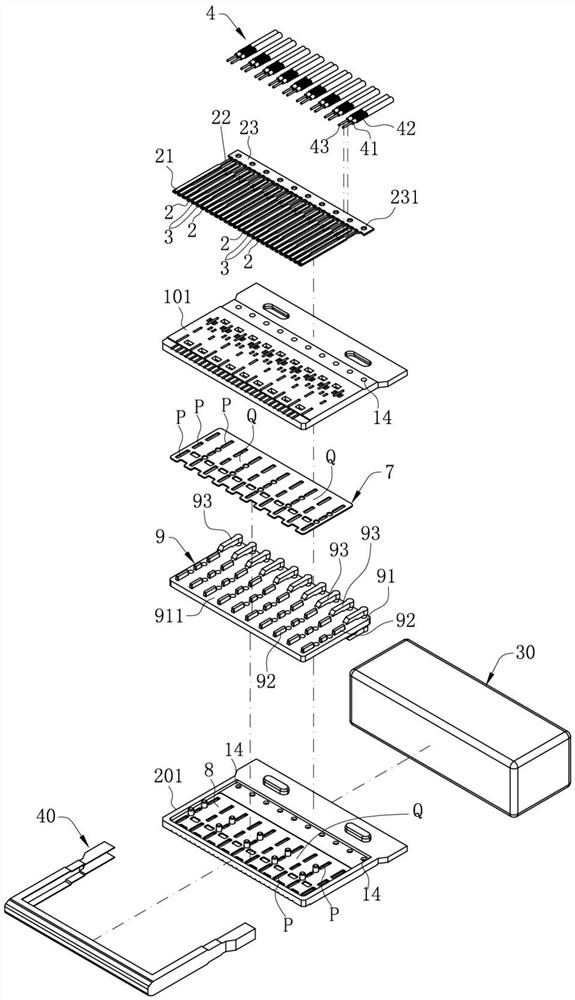
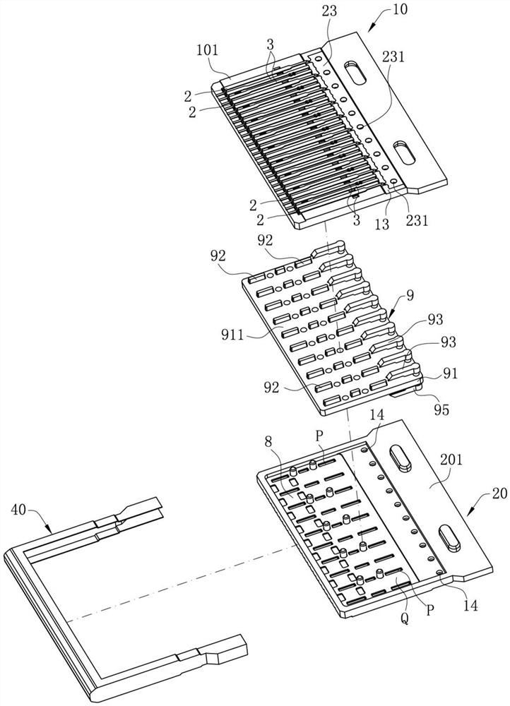
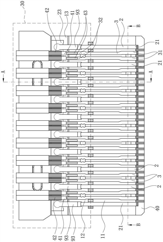
[0031] Such as Figure 1-7 As shown, it is the first embodiment of the present invention. The electrical connector of the present invention is used to dock with a mating connector (not shown) along the front...


PUM


Abstract

The invention discloses an electrical connector. The first conductive part of the electrical connector abuts against the lower surface of the first grounding contact part on the docking part and is integrally connected with the first conductive part by providing a first conductive part on the conductive plastic. The second conductive part is in contact with the upper surface of the first extension part located behind the docking part, so that the conductive plastic can be in contact with the front section and the rear section of the first ground terminal at the same time to form a multi-point contact, which not only ensures that the conductive plastic is in contact with the ground The good conduction effect between the terminals further improves the grounding effect of the grounding terminal. In addition, since the first conducting part and the second conducting part are respectively located on the upper and lower surfaces of the first grounding terminal, the conductive plastic and the first grounding terminal The upper contact is more stable, ensuring the high-frequency transmission quality of the electrical connector.

Description

【Technical field】 [0001] The invention relates to an electrical connector, in particular to an electrical connector for transmitting high frequency. 【Background technique】 [0002] Electrical connectors with high-speed data transmission usually need shielding to enhance the grounding effect of the grounding terminal, thereby ensuring the transmission quality of high-frequency signals. There is an existing electrical connector, which includes an insulating body and is fixed in the insulating body alternately. Multiple signal terminal pairs and multiple grounding terminals are arranged. In the manufacturing process, the insulating body, each signal terminal pair and each grounding terminal are fixed together to form a terminal module, and then the conductive plastic block is assembled or injected on the terminal. The module is integrated, wherein, the conductive plastic block is in contact with the ground terminal in the terminal module, so as to realize the shielding effect. ...

Claims


Application Information

Patent Timeline
Patent Type & Authority Patents(China)
IPC IPC(8): H01R13/02H01R13/646H01R13/648
CPCH01R13/02H01R13/646H01R13/648
Inventor 张文昌王永福彭治国
Owner DEYI PRECISION ELECTRONIC IND CO LTD PANYU
Why Eureka
Try Eureka