A spiral liquid conductance adjustable temperature sensor

A temperature sensor, spiral technology, applied in thermometers, thermometers using electric/magnetic elements that are directly sensitive to heat, thermometer parts, etc., to achieve high precision, good stability, and novel structure effects

Active Publication Date: 2022-05-17
德州尧鼎光电科技有限公司
View PDF6 Cites 0 Cited by
  • Summary
  • Abstract
  • Description
  • Claims
  • Application Information

AI Technical Summary

Problems solved by technology

By adjusting the position between the current electrode and the voltage electrode, the conductance (or resistance) can be adjusted to eliminate the manufacturing tolerance; it is also possible to automatically adjust the distance between the two electrodes during the application process to achieve Elimination of drift error; the application of these technologies to temperature sensors has important scientific significance, but no specific structural design and products have been released yet

Method used


Image

  • A spiral liquid conductance adjustable temperature sensor
  • A spiral liquid conductance adjustable temperature sensor
  • A spiral liquid conductance adjustable temperature sensor

Examples


Embodiment 1

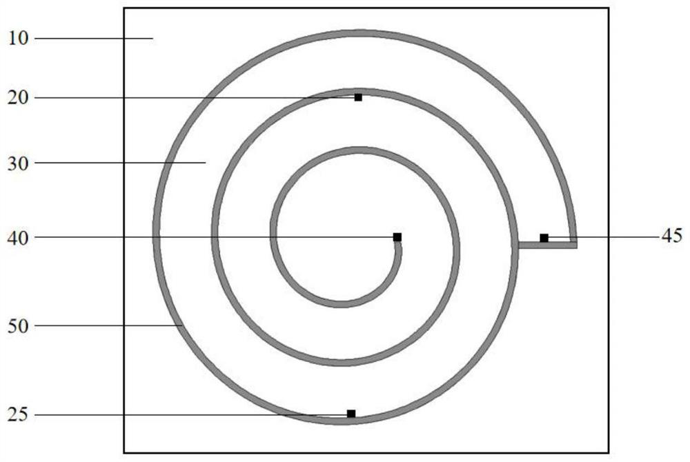
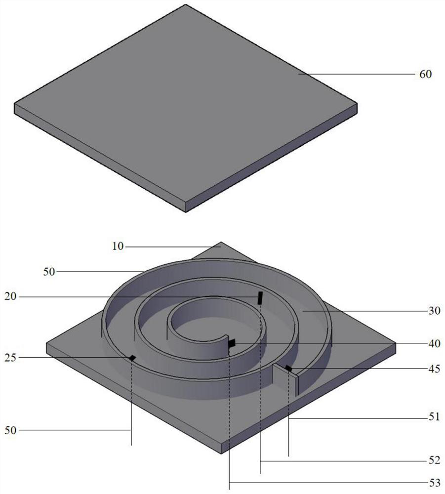
[0022]The spiral liquid conductance adjustable four-electrode temperature sensor involved in this embodiment has a main structure including a lower chassis 10, a first voltage electrode 20, a second voltage electrode 25, a liquid 30, a first current electrode 40, and a second current electrode 45 , spiral cavity 50, and the upper chassis 60 symmetrical to the lower chassis 10 and the homogeneous wires 51, 52, 53 and 54 of the connecting electrodes; The cavity 50 is fixed with the first voltage electrode 20 and the second voltage electrode 25 respectively at the corresponding position of the cavity 50; A current electrode 40 and a second current electrode 45 are filled with the liquid 30 in the spiral cavity inside the cavity 50, and the upper side of the cavity 50 is sealed with an upper chassis 60; the upper chassis 60 corresponds to the structure of the lower chassis 10 , the two are hermetically combined to form a box-shaped spiral cavity 50 with a closed structure.

[002...

Embodiment 2

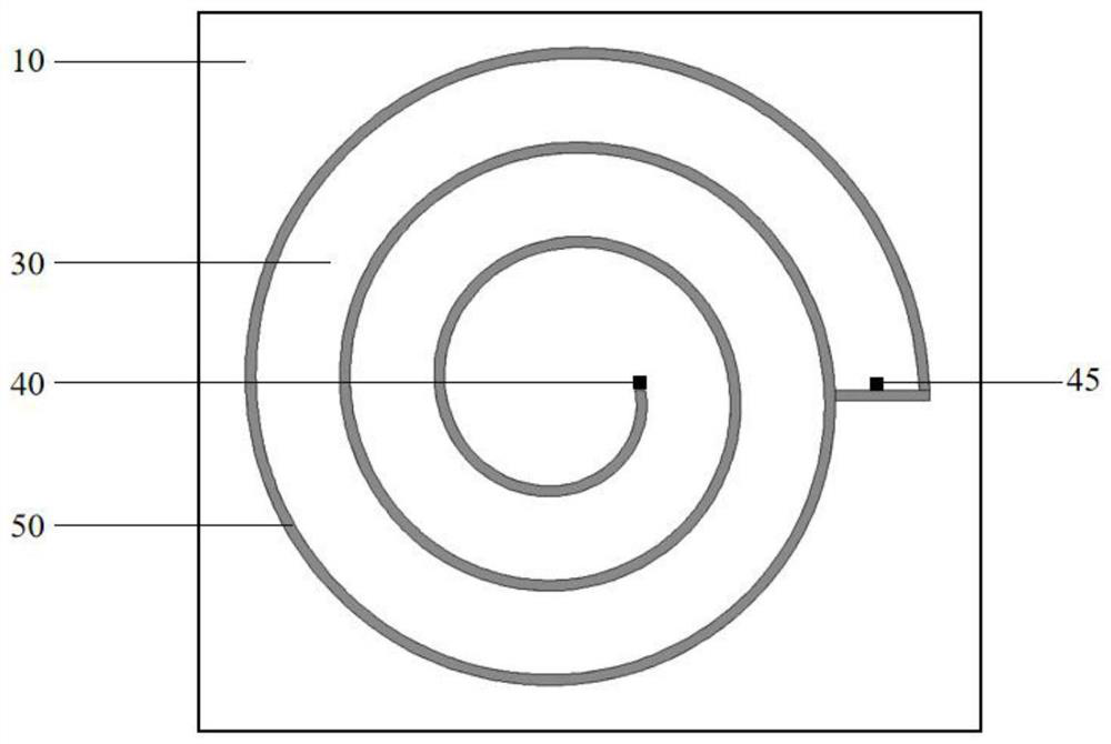
[0032] The main structure of the spiral two-electrode liquid conductance adjustable temperature sensor involved in this embodiment is similar to the four-electrode, including the lower chassis 10, the liquid 30, the first current electrode 40, the second current electrode 45 and the spiral cavity 50, As well as the upper chassis 60 symmetrical to the lower chassis 10 and the wires 51 and 53 connecting the electrodes, the connection principles and structures of the components correspond to those of the first embodiment.

[0033] For the two current electrodes involved in this embodiment, a constant AC excitation is applied to both ends, and the resistance value of the liquid 30 in the cavity 50 is obtained according to the measured voltage and current. The temperature can be deduced; the precise and stable measurement of the temperature under the external high pressure can be realized through the above structure.

[0034] The sensor involved in this embodiment can be applied to...


PUM


Abstract

The invention belongs to the technical field of temperature sensors, and relates to a spiral liquid conductance adjustable temperature sensor. A spiral cavity is formed on the lower chassis of a square or circular plate structure, and a spiral cavity is fixed at the corresponding position of the cavity. First and second voltage electrodes; first and second current electrodes are respectively fixed on the inside of the inner end and the outer end of the helical cavity, and the inside of the cavity is filled with the liquid in the helical cavity, the cavity The upper side is sealed with an upper chassis; the structure of the upper chassis and the lower chassis are corresponding, and the two are sealed and combined to form a box-shaped spiral cavity with a closed structure. The design principle is scientific and reliable, and the structure is novel and simple. Affected by external and self-stress, the conductance value can be adjusted at any time, and has the advantages of small size, high precision, good stability, and high integration.

Description

Technical field: [0001] The invention belongs to the technical field of temperature sensors, and relates to a spiral liquid conductance adjustable temperature sensor and its structural design. The temperature measurement is realized based on the characteristic that the conductivity of the liquid changes linearly with the temperature, and the temperature of the thermometer is realized by fine-tuning the position of the electrodes of the conductance cell. Highly accurate calibration. Background technique: [0002] In the existing sensor technology field, especially in the application occasions involved in the temperature sensor technology, temperature is a very important and special basic physical quantity, and the measurement of temperature is an important branch in the field of metrology technology. Every link in scientific research and industrial and agricultural production is inseparable from the reliable and accurate measurement of temperature. The accurate measurement of...

Claims


Application Information

Patent Timeline
Patent Type & Authority Patents(China)
IPC IPC(8): G01K7/28G01K1/12
CPCG01K7/28G01K1/12
Inventor 吴锜刘海玲高莉媛
Owner 德州尧鼎光电科技有限公司
Why Eureka
Try Eureka