
Form device and form system

A formwork and side plate technology, which is applied in the field of formwork devices and formwork systems, can solve problems such as reducing the corner strength of the road surface and road surface cracks, and achieve the effect of ensuring quality, ensuring strength and avoiding road surface cracks.

Active Publication Date: 2020-11-24
CHINA FIRST METALLURGICAL GROUP
View PDF12 Cites 3 Cited by
  • Summary
  • Abstract
  • Description
  • Claims
  • Application Information

AI Technical Summary

Problems solved by technology

[0003] In view of this, the present invention proposes a formwork device, which aims to solve the problem in the prior art that the formwork is removed first and then the slits are easily reduced to reduce the strength of the corners of the road surface and cause cracks on the road surface

Method used


Image

  • Form device and form system
  • Form device and form system
  • Form device and form system

Examples


Embodiment Construction

[0024] Exemplary embodiments of the present disclosure will be described in more detail below with reference to the accompanying drawings. Although exemplary embodiments of the present disclosure are shown in the drawings, it should be understood that the present disclosure may be embodied in various forms and should not be limited by the embodiments set forth herein. Rather, these embodiments are provided for more thorough understanding of the present disclosure and to fully convey the scope of the present disclosure to those skilled in the art. It should be noted that, in the case of no conflict, the embodiments of the present invention and the features in the embodiments can be combined with each other. The present invention will be described in detail below with reference to the accompanying drawings and examples.

[0025] Template device embodiment:

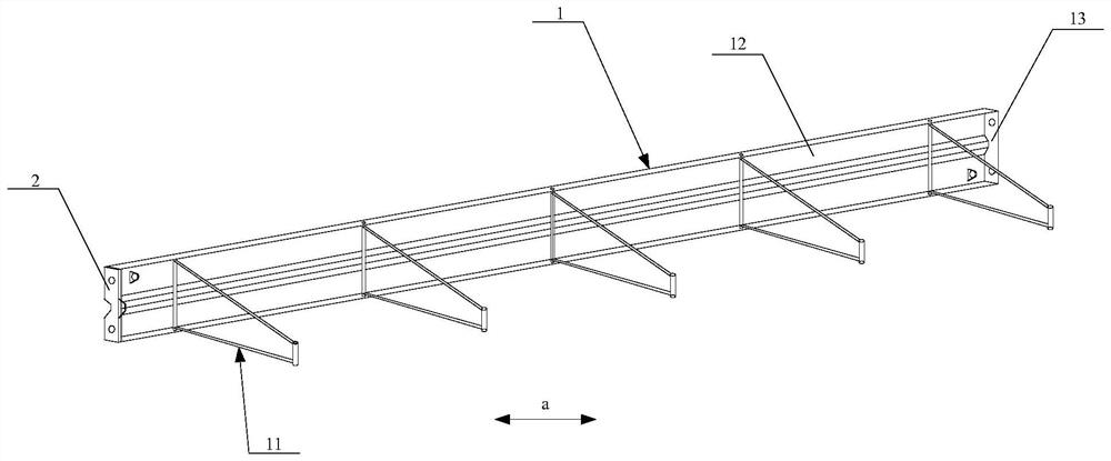
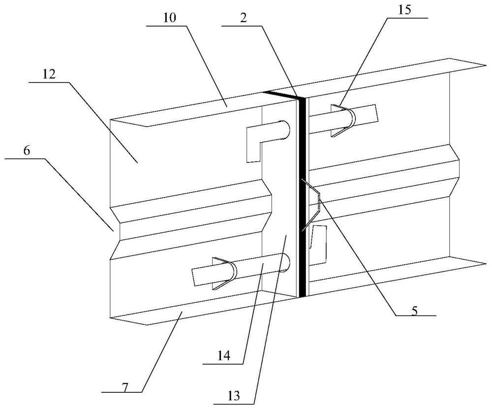
[0026] see Figure 1 to Figure 5 , the figure shows the preferred structure of the template device in this embodiment. ...


PUM


Abstract

The invention provides a form device and a form system. The form device comprises two form structures and a joint cutting plate; the two form structures are oppositely arranged, each form structure isused for shaping poured concrete; and the joint cutting plate is clamped between the two form structures in a drawable manner. According to the form device and the form system, the two form structures support the poured concrete to ensure that the concrete can be stably shaped, when the concrete reaches a preset degree, the joint cutting plate can be pulled out from the space between the two formstructures, and then joint cutting is carried out according to a gap between the two form structures after the joint cutting plate is pulled out, and the two form structures do not need to be dismounted during joint cutting, so that joint cutting and form dismounting are carried out in sequence according to the standard process, joint cutting is carried out in time, the pavement quality is guaranteed, pavement cracks caused by untimely joint cutting are avoided, the strength of all parts of the concrete is guaranteed, and the overall quality of the poured concrete is improved.

Description

technical field [0001] The invention relates to the technical field of construction, in particular to a formwork device and a formwork system. Background technique [0002] At present, after the construction of cement concrete roads, the cement concrete needs to be cut at intervals to prevent cracks. The purpose of the cuts is to make the cement concrete pavement shrink according to the position of the cuts, so that the stress is released. In order to effectively control road cracks, it is necessary to cut the cracks as early as possible. According to the standard construction process, the seam should be cut first, and then the side formwork should be removed. However, the formwork used for existing road construction is usually removed first and then cut. In this way, the premature removal of the formwork will easily cause the corners of the road surface to lack edges and corners due to insufficient strength, and it is easy to cause the cutting seam to be untimely. There a...

Claims


Application Information

Patent Timeline
Patent Type & Authority Applications(China)
IPC IPC(8): E01C19/50E01C23/02
CPCE01C19/50E01C23/02
Inventor 刘奎余珊鲁丙奎廖红玉孙广宏黄达锴郝国珍
Owner CHINA FIRST METALLURGICAL GROUP
Learn More