
Large thermal insulation box equipment based on independent node installation

A technology of independent nodes and heat preservation boxes, applied in the field of industrial heat preservation, can solve the problems of increased difficulty in processing and manufacturing heat preservation boxes, increased maintenance and repair costs, increased difficulty, and low applicability of temperature sensors, so as to eliminate the problem of weak engagement and avoid Effect of sensor damage and heat loss reduction

Inactive Publication Date: 2020-11-24
合肥青鸾新能源科技有限公司
View PDF0 Cites 0 Cited by
  • Summary
  • Abstract
  • Description
  • Claims
  • Application Information

AI Technical Summary

Problems solved by technology

[0004] Although the above-mentioned technical method has realized the temperature sensing detection of each position inside the insulation box, there are some problems in setting sensors inside the insulation box: first, the temperature sensor is installed inside the insulation box, causing the insulation box itself The difficulty of processing and manufacturing increases, and the cost and difficulty of maintenance and repair increase; secondly, the temperature sensor is installed inside the insulation box, and when some corrosive liquefied raw materials are stored, the temperature sensor may be damaged, so Less applicability of internally set temperature sensor

Method used


Image

  • Large thermal insulation box equipment based on independent node installation
  • Large thermal insulation box equipment based on independent node installation
  • Large thermal insulation box equipment based on independent node installation

Examples


Embodiment 1

[0041] like Figure 1 to Figure 8 , The invention is a large-scale incubator equipment based on independent node installation and measurement and control.

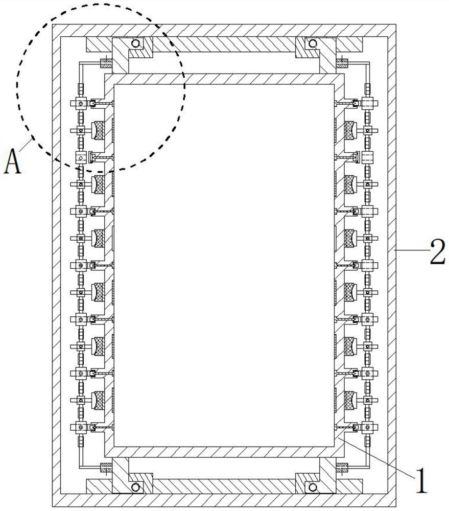
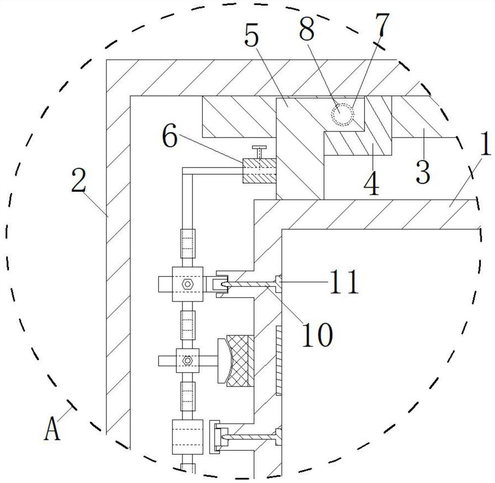
[0042] see figure 2 , the outer periphery of the heat preservation box 1 is provided with a peripheral installation base shell 2, the inner side of the outer periphery installation base shell 2 is fixedly installed with a first inner fixed strip 3, and the outer side of the heat preservation box 1 is fixedly connected with a second locking flap 5. A second conductive contact groove 7 is provided on the second clamping flap 5; a first conductive contact groove 7 matched with the second conductive contact groove 7 on the second clamping flap 5 is provided on the first inner fixed strip 3. Conductive plug 8.

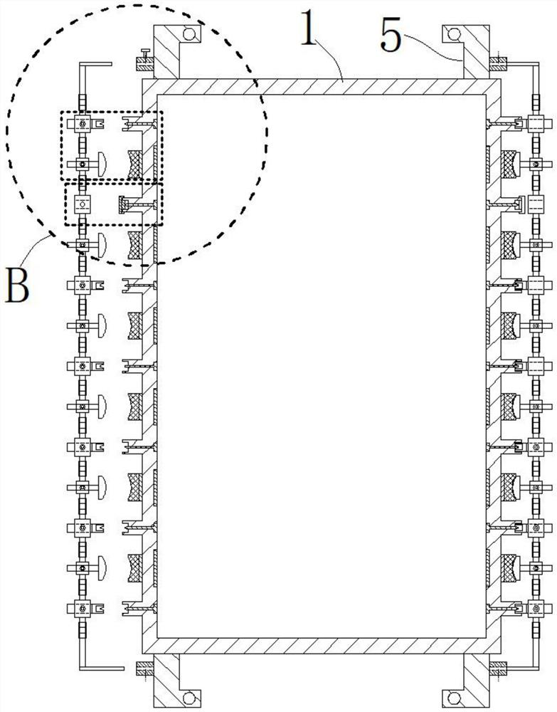
[0043] see figure 2 , Figure 5 , the outer side of the heat preservation box 1 is evenly provided with some convex columns 9 outside the box; The inner heat conduction rod 10 at the position; the outer surface o...


PUM


Abstract

The invention discloses large thermal insulation box equipment based on independent node installation and relates to the technical field of industrial thermal insulation. A plurality of uniformly-distributed inner-side electric heating pieces are embedded into the inner side of a thermal insulation box body. Inner-side heat conducting bars located on positions of box body outer convex columns arearranged in the thermal insulation box body. Outer-position open grooves are formed in the outer side faces of the box body outer convex columns. Cone outer heads located in the outer-position open grooves are arranged at the outer side ends of the inner-side heat conducting bars. A plurality of outer-side magnetic suction blocks located between adjacent box body outer convex columns are arrangedon the outer side faces of the thermal insulation box body. First installing base blocks matched with positions of the box body outer convex columns are arranged on the periphery of the thermal insulation body. A plurality of second installing base blocks in cooperation with positions of the outer-side magnetic suction blocks are arranged on the periphery of the thermal insulation box body. By means of the large thermal insulation box equipment based on independent node installation, installation of temperature sensors is convenient, efficient and stable; conducting of multidirectional, multi-node high-precision temperature measurement and auxiliary heating on large thermal insulation box bodies is achieved; and maintenance and repair operation of the sensors is also convenient.

Description

technical field [0001] The invention belongs to the technical field of industrial heat preservation, and in particular relates to a large-scale heat preservation box equipment based on independent node installation and measurement and control. Background technique [0002] In industrial production, there are some materials and raw materials that need to be stored at constant temperature or heat preservation. When carrying out heat preservation storage of industrial raw materials and materials, the size of the heat preservation box used is also very large, so more one-time storage of materials. However, when the actual industrial materials are stored at a constant temperature, there are fewer temperature measurement nodes, and the size of the insulation body is large, resulting in a large difference between the temperature of the material at each position in the box and the standard value. [0003] In the prior art, there are many levels of temperature sensors installed insi...

Claims


Application Information

Patent Timeline
IPC IPC(8): B65D88/74B65D90/00B65D90/02B65D90/48
CPCB65D88/744B65D90/00B65D90/02B65D90/48
Inventor 朱鸣飞
Owner 合肥青鸾新能源科技有限公司
Learn More