Invoice stamping machine

A technology for stamping machines and invoices, applied in printing, stamping and other directions, can solve the problems of unguaranteed ink, cumbersome, low efficiency of replacing stamps, etc., and achieve the effect of outstanding substantive features, wide application prospects, and reliable design principles.

Inactive Publication Date: 2020-11-24
国网山东省电力公司安丘市供电公司 +1
View PDF0 Cites 0 Cited by
  • Summary
  • Abstract
  • Description
  • Claims
  • Application Information

AI Technical Summary

Problems solved by technology

[0003] Document stamping is an operation often used in business processing. Traditional stamping is done manually by the staff. When there are few documents that need to be stamped, the manual stamping method can still be applied, but when a large number of documents need to be When stamping, the manual stamping method cannot meet the needs of high-efficiency work due to the low efficiency of stamping; The particularity of the effectiveness, the clear seal and the exact position of the seal can become a legal certificate
[0004] In the existing invoice stamping machine, the ink on the seal cannot guarantee the clarity of the seal after stamping multiple documents. Since the stamped document has the particularity of legal effect, it is particularly important to have a clear seal during the stamping process. , and due to the different attributes of the documents, the seals that need to be stamped are different. The traditional invoice stamping machine needs to manually replace the seal, which is very cumbersome. When the documents need to be stamped, the work method of manually changing the stamp cannot meet the needs of high-efficiency work due to the low efficiency of stamping.

Method used


Image

  • Invoice stamping machine
  • Invoice stamping machine
  • Invoice stamping machine

Examples


Embodiment Construction

[0028] The present invention will be described in detail below with reference to the accompanying drawings and specific embodiments. The following embodiments are explanations of the present invention, but the present invention is not limited to the following embodiments.

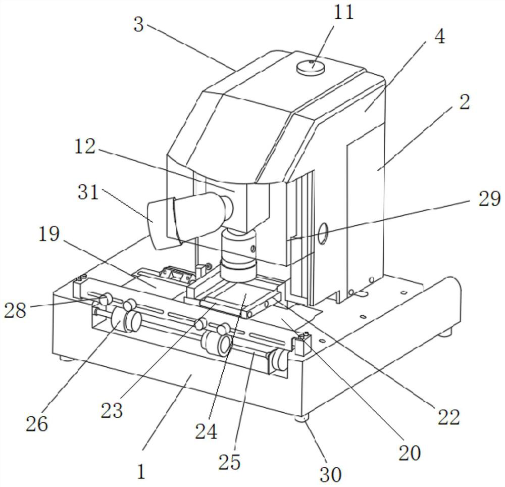
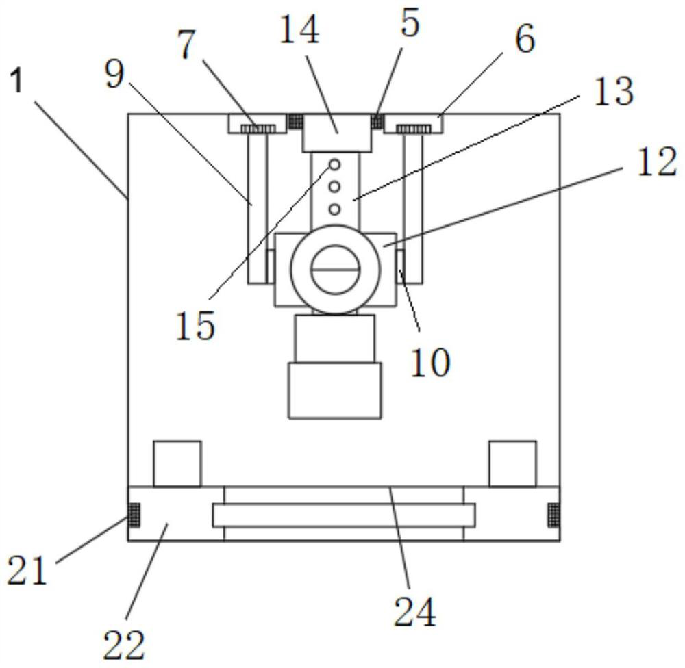
[0029] Such as Figure 1-3 As shown, a kind of invoice stamping machine provided by this embodiment includes:

[0030] The base 1, the base 1 is provided with a housing 2, the housing 2 includes a top wall 3 and two side walls 4, the inner side of the top wall 3 is provided with an upper slide rail 5, and the two sides of the upper slide rail 5 An upper slider 6 is provided at the end, and a hydraulic motor 7 is connected to each of the two upper sliders. The hydraulic motor 7 is connected to the controller 8, and the output end of the hydraulic motor 7 is connected to a hydraulic rod 9, and the end of the hydraulic rod 9 is connected to There is a rotating shaft 10, and the rotating shaft 10 is vertically...


PUM


Abstract

The invention relates to an invoice stamping machine which comprises a base. The base is provided with a shell, the shell comprises a top wall and two side walls, the inner side of the top wall is provided with an upper sliding rail, the two ends of the upper sliding rail are provided with upper sliding blocks, the two upper sliding blocks are each connected with a hydraulic motor, the hydraulic motors are connected with a controller, the output ends of the hydraulic motors are connected with hydraulic rods, the tail ends of the hydraulic rods are connected with rotating shafts, and the rotating shafts are perpendicular to the hydraulic rods. The controller is connected with a button, and the button is arranged on the top wall of the shell. The invoice stamping machine further comprises arotary connecting block, the left side wall and the right side wall of the rotary connecting block are connected to the two rotating shafts correspondingly, and the front side wall, the rear side walland the bottom wall of the rotary connecting block are each provided with a stamp; and the top wall of the rotary connecting block is connected with a connecting hose, the connecting hose is matchedwith the upper sliding rail through a hose sliding block, the connecting hose is provided with a connecting hole, the connecting hole is connected with an ink guide hose, and the ink guide hose is connected to an ink box through a micro high-pressure pump.

Description

technical field [0001] The invention belongs to stamping machine equipment, in particular to an invoice stamping machine. Background technique [0002] At present, the electricity invoices issued by the State Grid are divided into three invoices. The first invoice is used as a stub for future reference, the second invoice is sent to the user as the original voucher for remittance or receipt, and the third invoice is used as the bookkeeping page. The original document for bookkeeping. [0003] Document stamping is an operation often used in business processing. Traditional stamping is done manually by the staff. When there are few documents that need to be stamped, the manual stamping method can still be applied, but when a large number of documents need to be During the stamping process, the manual stamping method cannot meet the high-efficiency work needs due to the low efficiency of stamping; The particularity of effectiveness, the clear seal and the exact position of th...

Claims


Application Information

Patent Timeline
Patent Type & Authority Applications(China)
IPC IPC(8): B41K3/04B41K3/54B41K3/62
CPCB41K3/04B41K3/54B41K3/62
Inventor 张静雯方丽张晓鹏王晓晓王志达李金莲李大双宋丹张晓辉赵建鹏
Owner 国网山东省电力公司安丘市供电公司
Why Eureka
Try Eureka