Glue inlet device with latent side sprue

A side gate and glue feeding technology is applied in the field of glue feeding devices for latent side gates, which can solve the problems of mold sticking and casting head flying.

Inactive Publication Date: 2020-11-24
遵义群建塑胶制品有限公司
View PDF4 Cites 0 Cited by
  • Summary
  • Abstract
  • Description
  • Claims
  • Application Information

AI Technical Summary

Problems solved by technology

[0004] The present invention intends to provide a latent side gate glue feeding device to solve the problem in the prior art that the mold is stuck due to the flying of the pouring material head

Method used


Image

  • Glue inlet device with latent side sprue
  • Glue inlet device with latent side sprue
  • Glue inlet device with latent side sprue

Examples


Embodiment Construction

[0018] The following is further described in detail through specific implementation methods:

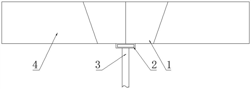
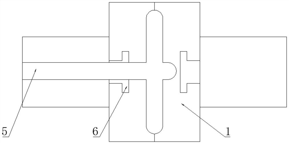
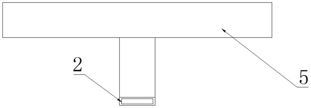
[0019] The reference signs in the drawings of the description include: gate plate 1 , side gate 2 , ejector pin 3 , punch 4 , runner 5 , and T-shaped plate 6 .

[0020] Examples such as figure 1 , figure 2 and image 3 As shown, a glue feeding device for a latent side gate includes a punch 4 and a die, the two sides of the punch 4 are welded with suspension rings, and a molding cavity is provided between the die and the punch 4 (shown in the figure ). The middle part of the punch 4 is provided with an installation port, and the installation port is provided with a runner 5 and a ejector pin 3 sequentially from top to bottom. The gate 2 and the side gate 2 communicate with the molding cavity. The inner wall of the installation port is inclined downward toward the ejector rod 3, and the inner wall of the installation port is correspondingly welded with a T-shaped plate 6. The sp...


PUM


Abstract

The invention discloses a glue inlet device with a latent side sprue, and belongs to the technical field of injection moulding equipment. The glue inlet device comprises a convex mould and a concave mould, wherein a moulding cavity is formed between the concave mould and the convex mould; a mounting hole is formed in the convex mould; a runner and an ejector rod are sequentially arranged in the mounting hole from top to bottom; the top of the ejector rod abuts against the bottom end of the runner; the runner communicates with the side sprue; the side sprue communicates with the moulding cavity; the inner side wall of the mounting hole tilts downwards towards the ejector rod; the inner side walls of the mounting hole are correspondingly in sliding connection to sprue plates separately in atilting direction; and the top of the runner abuts against the bottoms of the sprue plates at the two sides. While the ejector rod ejects the runner and the side sprue, the side sprue can separate thesprue plates at the two sides, and can pass through from the sprue plates at the two sides; and the ejector rod ejects the runner, the side sprue and an injection moulded product to the outside of the convex mould, so that a poured material head is not bounced off while ejected out, and the side surface of the product is not damaged by pulling.

Description

technical field [0001] The invention relates to the technical field of injection molding equipment, in particular to a glue feeding device for a latent side gate. Background technique [0002] At present, when molds are used to manufacture plastic products, the glue feeding methods mainly include side gates and latent gates. The runners for latent gates are on the parting surface, and then processed obliquely (at a certain angle with the parting surface) The glue inlet, generally the glue inlet is selected on the side of the product. [0003] Although the glue inlet of the latent gate can be selected on the side of the product, it has certain flexibility, but the ejection of the latent gate is to use the runner ejector to forcibly push the runner, relying on the latent glue mouth being cut and the latent glue mouth However, due to the shearing of the latent glue port and the plastic deformation of the latent glue port, the side of the product is easy to be strained, and the...

Claims


Application Information

Patent Timeline
Patent Type & Authority Applications(China)
IPC IPC(8): B29C45/27B29C45/40
CPCB29C45/2708B29C45/4005
Inventor 李灿陈勇张荣涛吴代辉
Owner 遵义群建塑胶制品有限公司
Why Eureka
Try Eureka