Integrated cooking stove
A cooking stove and stove body technology, which is applied in the field of integrated cooking stoves, can solve the problems of increased kitchen space occupation, unsatisfactory user experience, and inability to move the pot cover, etc., to achieve high power transmission efficiency, high oil fume absorption efficiency, and easy lifting. The effect of the operation
- Summary
- Abstract
- Description
- Claims
- Application Information
AI Technical Summary
Problems solved by technology
Method used
Image
Examples
Embodiment 1
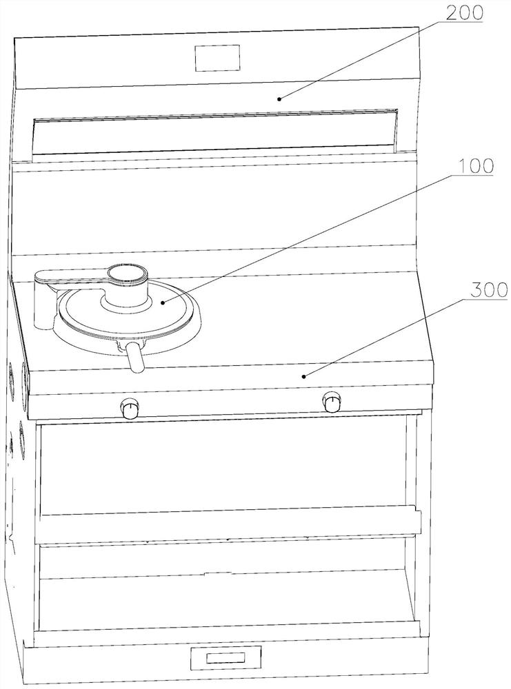
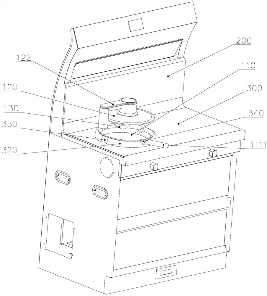
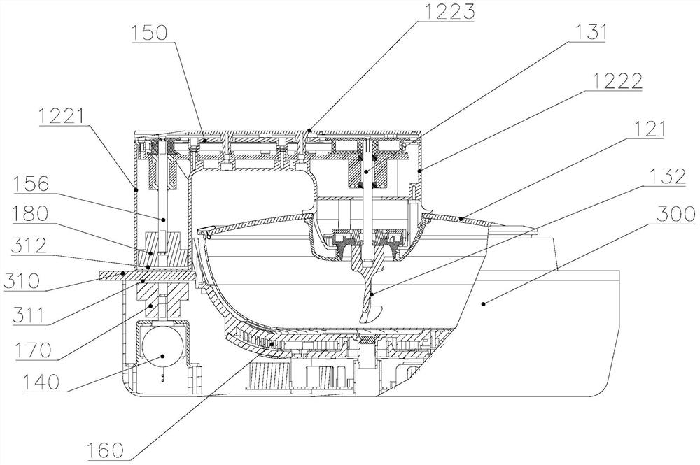
[0040] Such as Figure 1-6 As shown, the present invention proposes an integrated cooking stove, which includes a hood system 200 and a stove body 300 . Wherein, the cooking pot 100 is arranged on the top of the stove body 300 , the hood system 200 is set on one side of the top of the stove body 300 , and the air inlet of the hood system 200 is located above the cooking pot 100 . When the cooking pot 100 is in use, the hood system 200 can be activated in conjunction to extract the smoke generated when the cooking pot 100 is working. Since the water vapor generated by the cooking pot 100 is more concentrated and closer to the smoke inlet, the smoking effect is improved. Even better, it can effectively absorb oily fume, greatly reduce kitchen oily fume, purify the user's environment, and benefit the user's health; moreover, the high degree of integration of the integrated stove makes the kitchen more beautiful and effectively improves the user experience. The integrated cooker ...
Embodiment 2
[0057] The difference between this embodiment and the first embodiment lies in that the structure of the belt transmission assembly is different.
[0058] Such as Figure 7 and Figure 8 As shown, the end of the first pulley 151 and the second pulley 152 away from the mounting plate 1224 is provided with a baffle 154, and the baffle 154 is fixed on the first pulley 151 and the second pulley 152 by screws 155. The diameter of 154 is larger than the diameter of the corresponding pulley, so that the conveyor belt 153 is limited on the first pulley 151 and the second pulley 152, by fixing one end of the first pulley 151 and the second pulley 152 on the mounting plate 1224, And the other end of the first pulley 151 and the second pulley 152 is provided with a baffle plate 154, so that the conveyor belt 153 is limited between the two pulleys by the mounting plate 1224 and the baffle plate 154, ensuring the smoothness of the motion of the conveyor belt 153, so that The power can be...
Embodiment 3
[0062] The difference between this embodiment and Embodiment 1 and Embodiment 2 lies in that the structure and magnetic transmission mode of the active magnetic assembly and the driven magnetic assembly are different.
[0063] Such as Figure 9 and Figure 10 As shown, the active magnetic assembly 170 and the driven magnetic assembly 180 are nested and arranged to form a radial magnetic connection to form a circumferential-to-circumferential transmission. In order to realize that the end of the transmission arm 122 close to the active magnetic assembly 170 is nested with the cooker body 300, one of the cooker body 300 and the housing assembly is provided with a boss, and the other is provided with a ring that is sleeved and matched with the boss. The concave cavity and the convex platform cooperate with the concave cavity, so that the end of the shell component close to the active magnetic component 170 and the cooker body 300 are nested with each other.
[0064] Such as F...
PUM
 Abstract
Description
Claims
Application Information
 - Generate Ideas
- Intellectual Property
- Life Sciences
- Materials
- Tech Scout
- Unparalleled Data Quality
- Higher Quality Content
- 60% Fewer Hallucinations
Browse by: Latest US Patents, China's latest patents, Technical Efficacy Thesaurus, Application Domain, Technology Topic, Popular Technical Reports.
© 2025 PatSnap. All rights reserved.Legal|Privacy policy|Modern Slavery Act Transparency Statement|Sitemap|About US| Contact US: help@patsnap.com


