


Quick Research
Generate reliable direction feasibility study reports for your R&D in just a few steps.

Technical Q&A
Discover and master advanced knowledge NOW. Basics, ideas, possibilities, all at once.

Find Solutions
As an expert in R&D theories, this can generate solutions to your technical problems instantly.

Evaluate Feasibility
Analyze your overall solution with one click, know your potential R&D risks in advance.

Monitor Landscape
Get weekly tech updates, stay abreast of the latest tech innovations and key insights.
Mobile terminal sounding assembly structure and mobile terminal
A mobile terminal and component structure technology, applied in the direction of frequency/direction characteristic devices, etc., can solve the problem that the speaker hole cannot be located in the center, and achieve the effect of meeting the needs of appearance design
- Summary
- Abstract
- Description
- Claims
- Application Information
AI Technical Summary
Problems solved by technology
Method used
Image

Examples
Embodiment 1
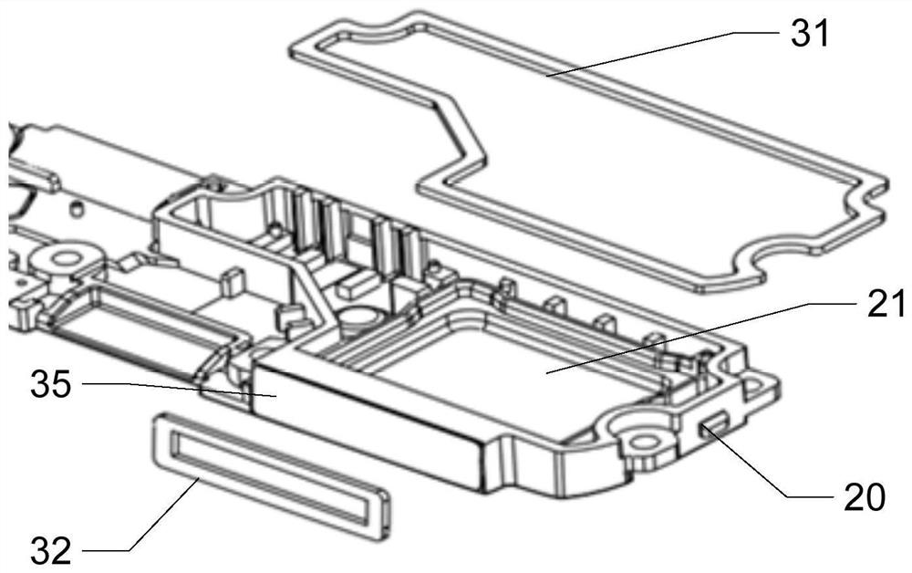
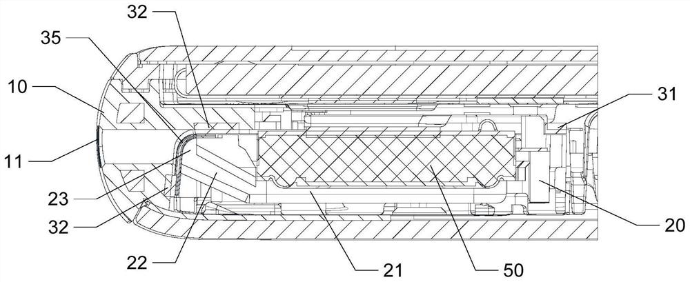
[0038] Such as Figure 3-Figure 5 As shown, the present invention proposes a mobile terminal pronunciation assembly structure, including: a housing 10, a horn 50, and a horn bracket 20; wherein, the horn 50 is arranged on the horn bracket 20, and the horn bracket 20 is provided with A sound cavity 21 and a sound output channel 22 , the sound output channel 22 is arranged on one side of the speaker bracket 20 , and the sound output channel 22 communicates with the sound cavity 21 .
[0039] In this embodiment, the housing 10 shown is generally a middle frame. Of course, there are cases where the middle frame and the rear case are integrated. This embodiment uses the middle frame as an illustration.
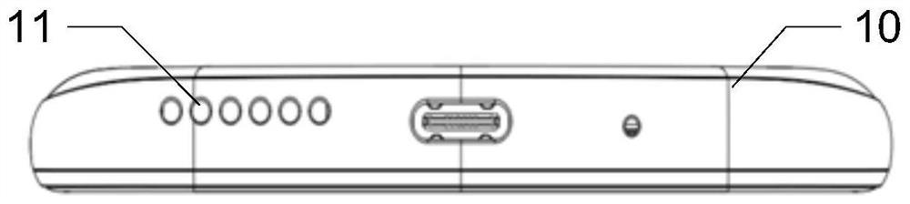
[0040] In this example, combined with Figure 6 As shown, the housing 10 is provided with a centered speaker hole 11 corresponding to the position of the speaker sound channel 22, that is to say, the speaker hole 11 is in the center position in the thickness direction of the mobil...
Embodiment 2
[0048] refer to Figure 3-Figure 5 , the present embodiment provides a mobile terminal, which includes: a housing 10, a speaker 50, and a speaker bracket 20; And the sound output channel 22 , the sound output channel 22 is arranged on one side of the speaker bracket 20 , and the sound output channel 22 communicates with the sound cavity 21 .
[0049] In this embodiment, the housing 10 shown is generally a middle frame. Of course, there are cases where the middle frame and the rear case are integrated. This embodiment uses the middle frame as an illustration.
[0050] In this embodiment, the housing 10 is provided with a centered speaker hole 11 corresponding to the position of the speaker sound outlet channel 22, that is to say, the speaker hole 11 is in the center position in the thickness direction of the mobile terminal, ensuring that the mobile terminal The appearance setting requirements of the lower horn hole 11.
[0051] Such as Figure 4 Shown is a schematic diagram...
PUM
 Abstract
Description
Claims
Application Information
 - R&D Engineer
- R&D Manager
- IP Professional
- Industry Leading Data Capabilities
- Powerful AI technology
- Patent DNA Extraction
Browse by: Latest US Patents, China's latest patents, Technical Efficacy Thesaurus, Application Domain, Technology Topic, Popular Technical Reports.
© 2024 PatSnap. All rights reserved.Legal|Privacy policy|Modern Slavery Act Transparency Statement|Sitemap|About US| Contact US: help@patsnap.com