
Antenna structure, signal transceiver module and impedance debugging method of antenna structure

A technology of antenna structure and debugging method, applied in the field of communication, can solve the problems of the increase of the number of antennas and the harsh environment of the antenna of the terminal product, and achieve the effect of reducing the spacing requirements, meeting the requirements of the appearance design, and improving the coupling degree of the antennas.

Active Publication Date: 2021-10-19
ZTE CORP
View PDF14 Cites 0 Cited by
  • Summary
  • Abstract
  • Description
  • Claims
  • Application Information

AI Technical Summary

Problems solved by technology

On the other hand, 5G communication technology requires a wider bandwidth than 2G / 3G / 4G communication technology, which doubles the number of antennas in terminal products, resulting in a worse antenna environment for terminal products

Method used


Image

  • Antenna structure, signal transceiver module and impedance debugging method of antenna structure
  • Antenna structure, signal transceiver module and impedance debugging method of antenna structure
  • Antenna structure, signal transceiver module and impedance debugging method of antenna structure

Examples


Embodiment Construction

[0026] In order to enable those skilled in the art to better understand the technical solution of the present invention, the antenna structure, signal transceiving module and antenna structure impedance debugging method provided by the present invention will be described in detail below with reference to the accompanying drawings.

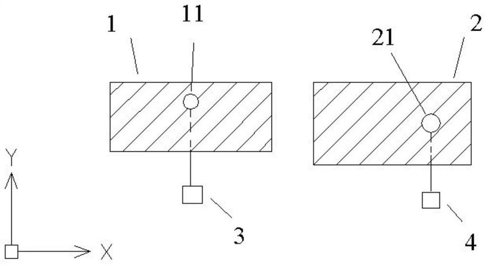
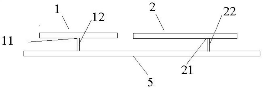
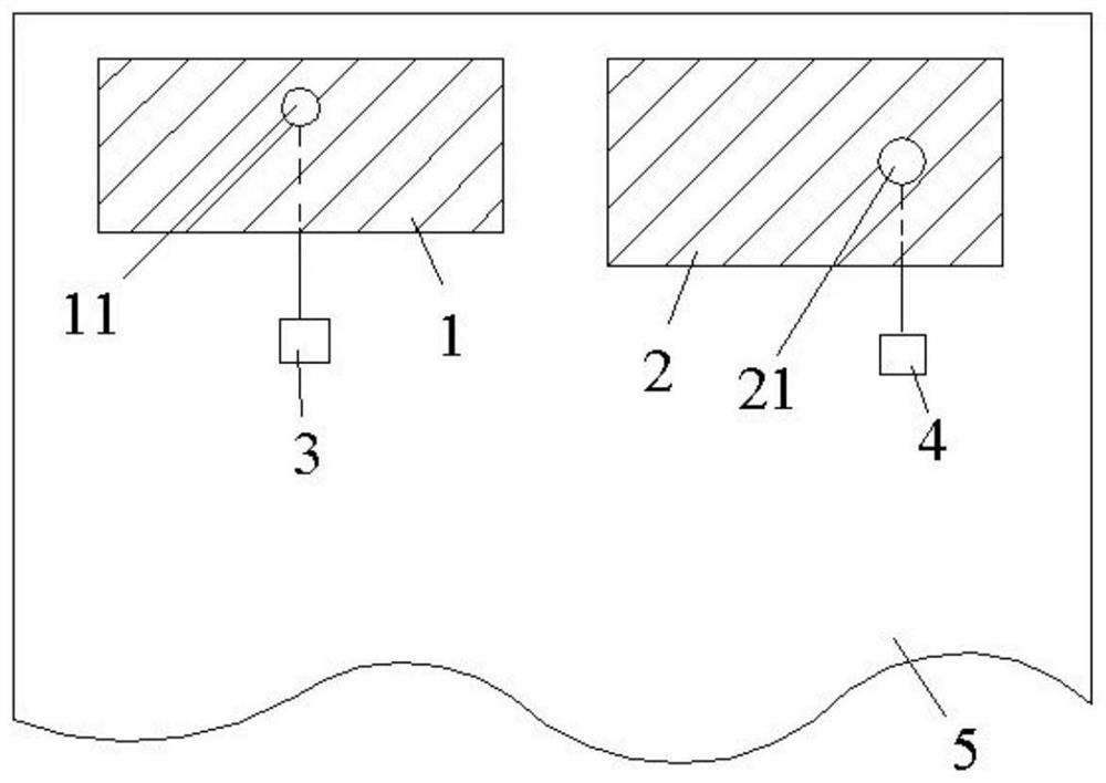
[0027] see figure 1 , the antenna structure provided in this embodiment includes a plurality of antennas, and each antenna has a feeding point for connecting with a matching circuit capable of adjusting the antenna impedance. In this embodiment, the two adjacent antennas shown are respectively For the first antenna 1 and the second antenna 2, the two have a first feed point 11 and a second feed point 21 respectively, wherein the first feed point 11 is connected to the first matching circuit 3; the second feed point 21 is connected to the second matching circuit 4 .

[0028] Moreover, the position of each feeding point on the antenna is set so that...


PUM


Abstract

The invention provides an antenna structure, a signal transceiving module and an antenna structure impedance debugging method. The antenna structure includes a plurality of antennas, and each antenna has a feeding point for connecting with a matching circuit, and the feeding point is located on the antenna. The position is set so that the polarized waves generated by the antenna where the feed point is located and the polarized waves generated by the adjacent antenna are orthogonal to each other. The antenna structure, the signal transceiver module and the technical scheme of the antenna structure impedance debugging method provided by the present invention can reduce the coupling degree between two adjacent antennas, thereby improving the antenna coupling degree, ensuring the antenna performance, and reducing the The space between the antennas is required, so that the antenna layout space can be saved, and the appearance design requirements of the terminal products can be met.

Description

technical field [0001] The present invention relates to the technical field of communication, in particular to an antenna structure, a signal transceiving module and an impedance debugging method of the antenna structure. Background technique [0002] With the accelerated maturity of 5G communication technology standards, the pace of 5G network deployment around the world is also getting faster and faster, and we are about to enter the 5G era. The ultra-large bandwidth, ultra-low latency, and high reliability of the 5G network will, on the one hand, bring innovations to ten major industries such as education, medical care, smart manufacturing, and Internet of Vehicles. On the other hand, 5G communication technology requires wider bandwidth than 2G / 3G / 4G communication technology, which doubles the number of antennas in terminal products, resulting in a worse antenna environment for terminal products. [0003] At present, the increase in the number of antennas will bring diff...

Claims


Application Information

Patent Timeline
Patent Type & Authority Patents(China)
IPC IPC(8): H01Q1/50H01Q1/52H04B1/40
CPCH01Q1/50H01Q1/521H04B1/40
Inventor 郑小飞
Owner ZTE CORP
Learn More