Pedal information sensing device and bicycle
A sensing device and signal detection technology, which is applied to measurement devices, motor vehicles, transportation and packaging, etc., can solve the problems of high cost and increase the complexity of the logic judgment of the program safety of the microcontroller, and achieve low cost, simple structure, The effect of increasing sensitivity
- Summary
- Abstract
- Description
- Claims
- Application Information
AI Technical Summary
Problems solved by technology
Method used
Image
Examples
Embodiment 1
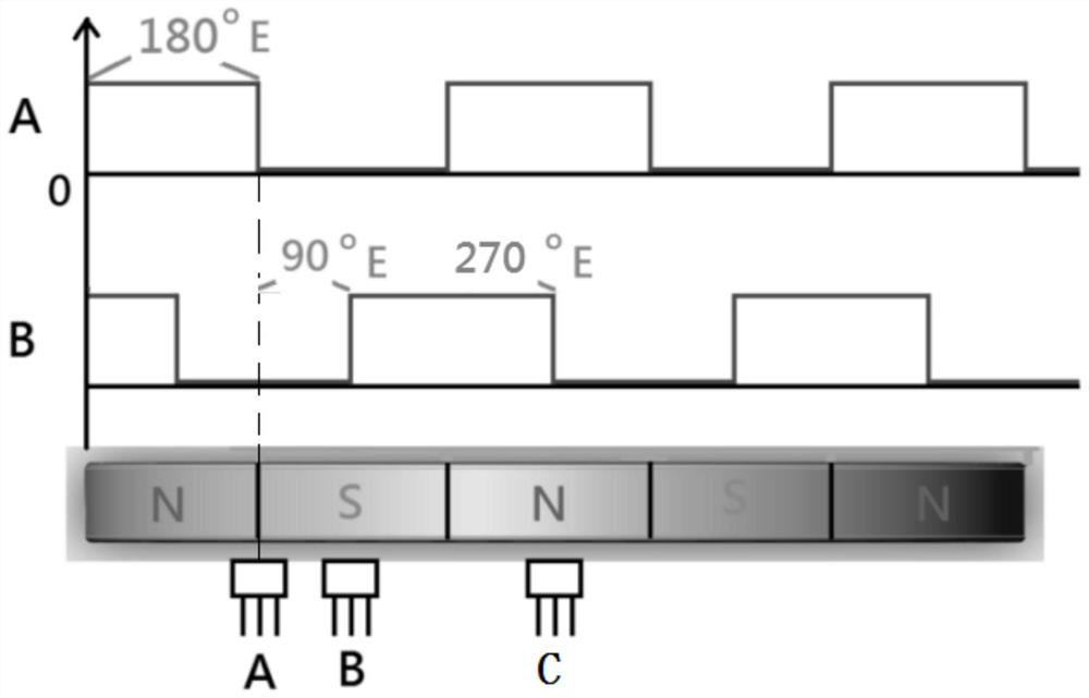
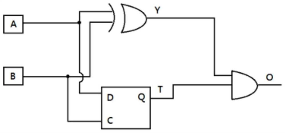
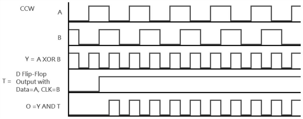
[0030] Such as figure 1 , 2 As shown, a pedal information sensing device includes a rotation signal generation part and a rotation signal detection part. The rotation signal generation part generates a periodic signal, that is, a periodically changing signal is formed on the rotation path, and the rotation signal detection part can detect these cycles The change of the signal, the rotation signal generating part is a magnetic ring, the rotation signal detection part is a Hall element A, a Hall element B, and the magnetic ring has magnetic poles distributed in the circumferential direction, and two adjacent magnetic rings The polarity of the magnetic poles is opposite, so that a periodically changing magnetic field is formed around the circumference of the magnetic ring. The corresponding magnetic poles on the magnetic ring are provided with Hall element A and Hall element B, so that the Hall element can feel the magnetic field at different positions relative to the magnetic ri...
Embodiment 2
[0036] There are still some deficiencies in the setting method of Embodiment 1, for example, as Figure 5As shown, when the forward rotation continues to output to the position of the marking line CCW->CW, the reversal occurs, that is, the Hall element A and the Hall element B are both at low potential. At this time, the first D flip-flop can immediately judge this state. That is to say, the first D flip-flop can easily change from a high potential to a continuous low potential, so that the output of the AND gate can simply reflect the change of the direction of the magnetic ring. However, if Image 6 As shown, when the inversion position occurs when Hall element A and Hall element B are both at high potential, the first D flip-flop needs to wait until the next trigger position before it can change to low potential, which will cause the output of the AND gate There will be an redundant waveform output on the controller, and this redundant signal will cause misjudgment to the ...
Embodiment 3
[0039] Such as Figure 9 As shown, the difference from the above embodiment is that the Hall element A and the Hall element B are connected to the second D flip-flop after passing through the NOT gate circuit, the exclusive OR gate circuit, the first D flip-flop and the second D flip-flop At the same time, the input of the NAND gate circuit is connected, and the output of the NAND gate circuit is connected to the base of the triode, so as to sense the change of the signal through the reflection of the triode.
PUM
 Abstract
Description
Claims
Application Information
 - R&D Engineer
- R&D Manager
- IP Professional
- Industry Leading Data Capabilities
- Powerful AI technology
- Patent DNA Extraction
Browse by: Latest US Patents, China's latest patents, Technical Efficacy Thesaurus, Application Domain, Technology Topic, Popular Technical Reports.
© 2024 PatSnap. All rights reserved.Legal|Privacy policy|Modern Slavery Act Transparency Statement|Sitemap|About US| Contact US: help@patsnap.com


