
Micro-shaft machining method

A processing method and micro-shaft technology, applied in the field of precision machining of mechanical components, can solve problems such as not being fine enough and unable to meet the process requirements of precision micro-shafts, so as to improve product quality, improve precision machining efficiency, improve surface quality and dimensional tolerance Effect

Inactive Publication Date: 2020-11-20
上海远葆知识产权服务有限公司
View PDF6 Cites 0 Cited by
  • Summary
  • Abstract
  • Description
  • Claims
  • Application Information

AI Technical Summary

Problems solved by technology

[0005] The deburring, heat treatment, cryogenic treatment, grinding, grinding and other processes in the prior art are not fine enough to meet the process requirements of precision miniature shafts

Method used


Image

  • Micro-shaft machining method

Examples


Embodiment Construction

[0030] It should be understood that the specific embodiments described here are only used to explain the present invention, not to limit the present invention.

[0031] The technical solutions in the embodiments of the present invention will be clearly and completely described below in conjunction with the accompanying drawings in the embodiments of the present invention. Obviously, the described embodiments are only part of the embodiments of the present invention, not all of them. example. Based on the embodiments of the present invention, all other embodiments obtained by persons of ordinary skill in the art without creative efforts fall within the protection scope of the present invention.

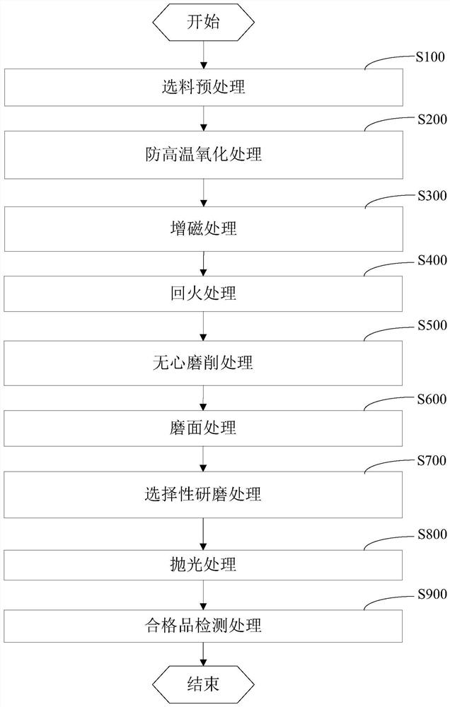
[0032] Reference attached figure 1 , is a schematic flow chart of a micro-shaft processing method in an embodiment of the present invention;

[0033] A processing method for a miniature shaft, comprising:

[0034] S100-Material selection pretreatment, choose the cylinder close to th...


PUM


Abstract

The invention provides a micro-shaft machining method which is applied to the technical field of mechanical component tight machining. Coarse blank is processed into qualified material through a specified technology, so that a micro-shaft assembled in electronic equipment has resistance value, magnetism and coercive force with low iron loss, the precision machining efficiency of the micro-shaft isimproved, the surface quality and dimensional tolerance of the micro-shaft are improved, and the product quality is improved.

Description

technical field [0001] The invention relates to the technical field of precision machining of mechanical components, in particular to a processing method for a miniature shaft. Background technique [0002] Micro shaft is a precision shaft with relatively small size and high precision. The main materials are carbon steel, stainless steel, copper or aluminum and other metal materials. The surface treatment mainly includes galvanizing, nickel, or carburizing, etc. It is mainly used in mobile phones Micro vibration motors, massagers, printers, copiers, shafts in auto parts, scanners or CD / VCD and other products. The main processing methods include punching the stainless steel wire to form a blank by a punching machine, and then performing heat treatment, grinding, surface treatment, turning, grinding and polishing, as well as sorting and packaging. The main processing equipment includes grinding machines, lathes, instrument cars, heat treatment, throwing cylinders, etc. The e...

Claims


Application Information

Patent Timeline
IPC IPC(8): B23P15/00B23P15/14
CPCB23P15/00B23P15/14
Inventor 苏宁
Owner 上海远葆知识产权服务有限公司
Learn More