
High-safety claw forging equipment

A high-security, hook-claw technology, applied in metal processing equipment, hooks, manufacturing tools, etc., can solve the problems of large tool damage, difficult edge removal, and increased hardness of forging blocks, achieving the effect of less heat loss and convenient removal

Active Publication Date: 2020-11-20
PUJIANG LEFT & RIGHT IND & TRADE CO LTD
View PDF8 Cites 0 Cited by
  • Summary
  • Abstract
  • Description
  • Claims
  • Application Information

AI Technical Summary

Problems solved by technology

[0002] In the production process of the claw hook, the metal segment is preliminarily bent after being fully heated and softened to form the basic shape of the hook, and then it is put into the mold for forging and pressing. The forging block completed by forging is removed by manual clamping and then sent to another equipment for edge removal. However, due to the heavy weight of the block during transportation, a certain amount of arm strength is required. At the same time, the inertia of heavy objects Larger, workers are often difficult to control, so there is a certain danger. At the same time, the heat loss of the forging block is large during the handling process, and the hardness of the forging block with heat loss will continue to rise, making it more difficult to remove the edge. The damage of the tool is relatively large, and the cost is relatively large. At the same time, the oxide scale produced by forging during the forging process usually needs to be removed manually. The manual method is often exposed to high-temperature environments, and long-term work is likely to affect the human body. On the other hand The manual method is prone to certain mistakes and there is a loss of equipment

Method used


Image

  • High-safety claw forging equipment
  • High-safety claw forging equipment
  • High-safety claw forging equipment

Examples


Embodiment Construction

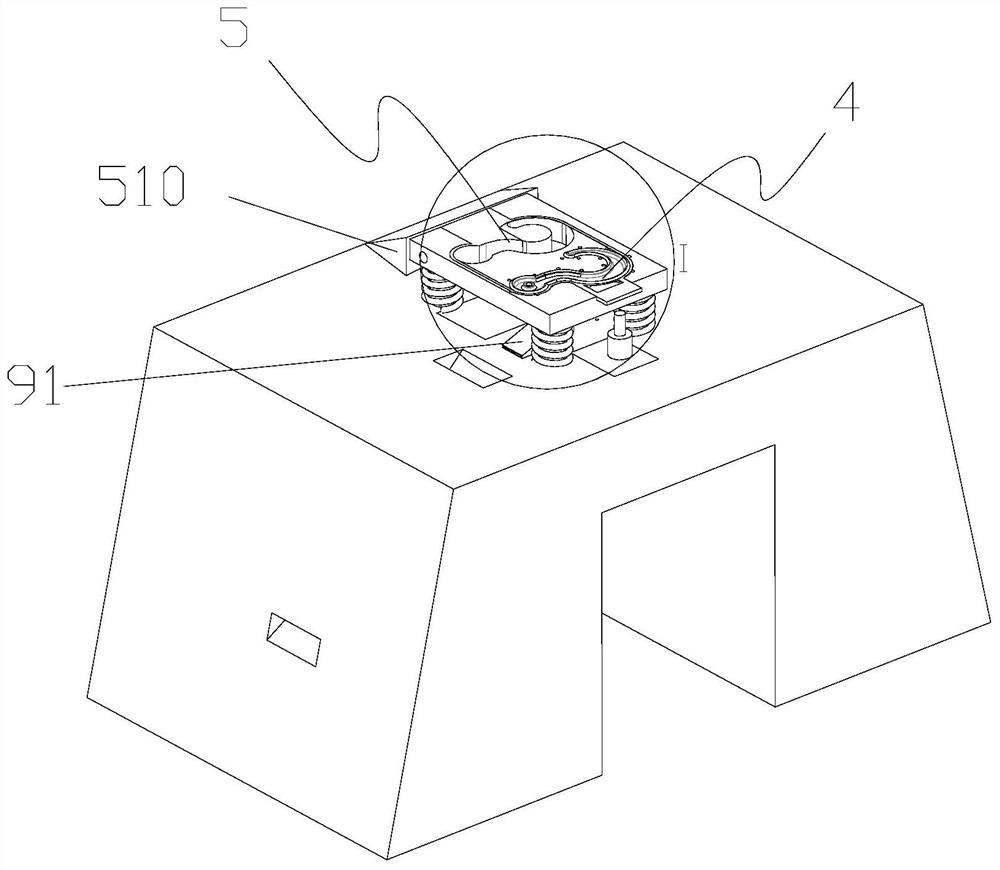
[0024] Such as Figure 1-11 As shown, a high-safety claw forging equipment includes a base 1, a frame 2, and a forging device 3; the base 1 is set on the ground, the frame 2 is set on the base, and the forging device 3 is set on the On the frame; the forging device 3 includes a hydraulic rod 31, a hydraulic hammer 32, a first slide rail 33, an upper die 34, a lower die 35, a forging structure 4, an edge removal structure 5, a shifting structure, and a first cleaning structure 6. The second cleaning structure 7; the hydraulic rod 31 is arranged on the frame, the hydraulic hammer 32 is arranged on the hydraulic rod, the first slide rail 33 is arranged on the frame, and the first slide rail is arranged on the On both sides of the frame, the upper mold 34 is arranged under the hydraulic hammer, the lower mold 35 is arranged on the base, the forging structure 4 is arranged on the lower mold, and the edge removal structure 5 is arranged on one side of the forging structure, The dis...


PUM


Abstract

The invention discloses high-safety claw forging equipment. The high-safety claw forging equipment comprises a base, a rack and a forging device; and the forging device comprises a hydraulic rod, a hydraulic hammer, a first sliding rail arranged on the rack, an upper die arranged below the hydraulic hammer, a lower die arranged on the base, a forging structure arranged on the lower die, an edge removing structure arranged on one side of the forging structure, a shifting structure used for moving materials from the forging structure to the edge removing structure, a first ash removing structurearranged on one side of the rack, and a second ash removing structure arranged on the other side of the rack. Through the arrangement of the shifting structure, the process of manually carrying a claw is omitted, so that the risk that workers are scalded in the carrying process is effectively avoided; the carrying distance is short, the heat loss is less in the carrying process, and consequentlythe edge removing can be more conveniently carried out; and meanwhile, through the arrangement of the first ash removing structure and the second ash removing structure, the labor cost is effectivelyreduced, and the safety of the workers is guaranteed.

Description

technical field [0001] The invention belongs to the technical field of claw hook production, and in particular relates to a high-safety claw forging equipment. Background technique [0002] In the production process of the claw hook, the metal segment is preliminarily bent after being fully heated and softened to form the basic shape of the hook, and then it is put into the mold for forging and pressing. The forging block completed by forging is removed by manual clamping and then sent to another equipment for edge removal. However, due to the heavy weight of the block during transportation, a certain amount of arm strength is required. At the same time, the inertia of heavy objects Larger, workers are often difficult to control, so there is a certain danger. At the same time, the heat loss of the forging block is large during the handling process, and the hardness of the forging block with heat loss will continue to rise, making it more difficult to remove the edge. The da...

Claims


Application Information

Patent Timeline
IPC IPC(8): B21K1/72B08B5/02B08B3/02B21K27/06B21J13/02B21J13/03B21J13/14
CPCB08B3/02B08B5/02B21J13/02B21J13/03B21J13/14B21K1/72B21K27/06
Inventor 董智勇洪超方青春
Owner PUJIANG LEFT & RIGHT IND & TRADE CO LTD
Learn More