
Lens module

A lens module and lens technology, applied in TV, color TV parts, TV system parts and other directions, can solve the problems of increasing the volume of the lens module, increasing the size of the lens module, and large movement space, and achieving Improve the effect of optical image stabilization, increase the degree of freedom of shake compensation, and the effect of small size

Inactive Publication Date: 2020-11-17
CHANGZHOU RAYTECH OPTRONICS CO LTD
View PDF6 Cites 6 Cited by
  • Summary
  • Abstract
  • Description
  • Claims
  • Application Information

AI Technical Summary

Problems solved by technology

However, the driving force of the autofocus component acts on the lens, and the driving force of the optical image stabilization component acts on the lens and sensor, so additional structural parts are required to connect the lens and the image sensor, thereby increasing the number of lens modules. Volume: the optical image stabilization component is used to move the entire camera module to achieve optical image stabilization. Under the same shake compensation angle, a large movement space needs to be reserved, which increases the size of the lens module in the direction of the optical axis

Method used


Image

  • Lens module
  • Lens module
  • Lens module

Examples


Embodiment Construction

[0029] The following will clearly and completely describe the technical solutions in the embodiments of the present invention with reference to the accompanying drawings in the embodiments of the present invention. Obviously, the described embodiments are only some, not all, embodiments of the present invention. Based on the embodiments of the present invention, all other embodiments obtained by persons of ordinary skill in the art without making creative efforts belong to the protection scope of the present invention.

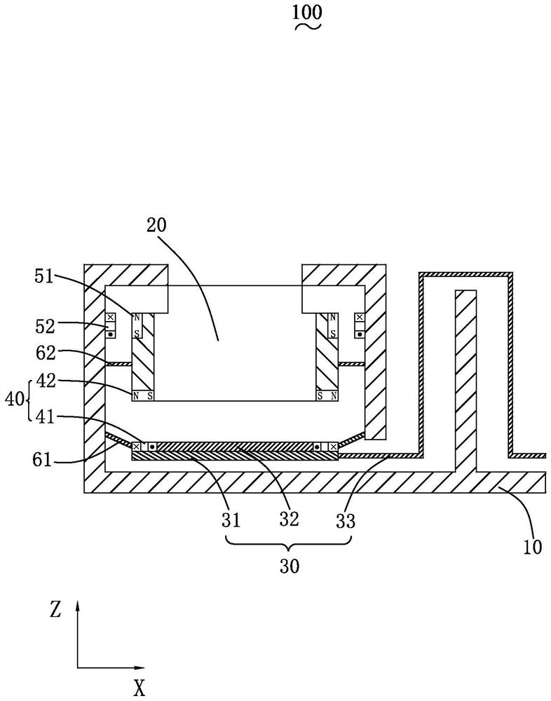
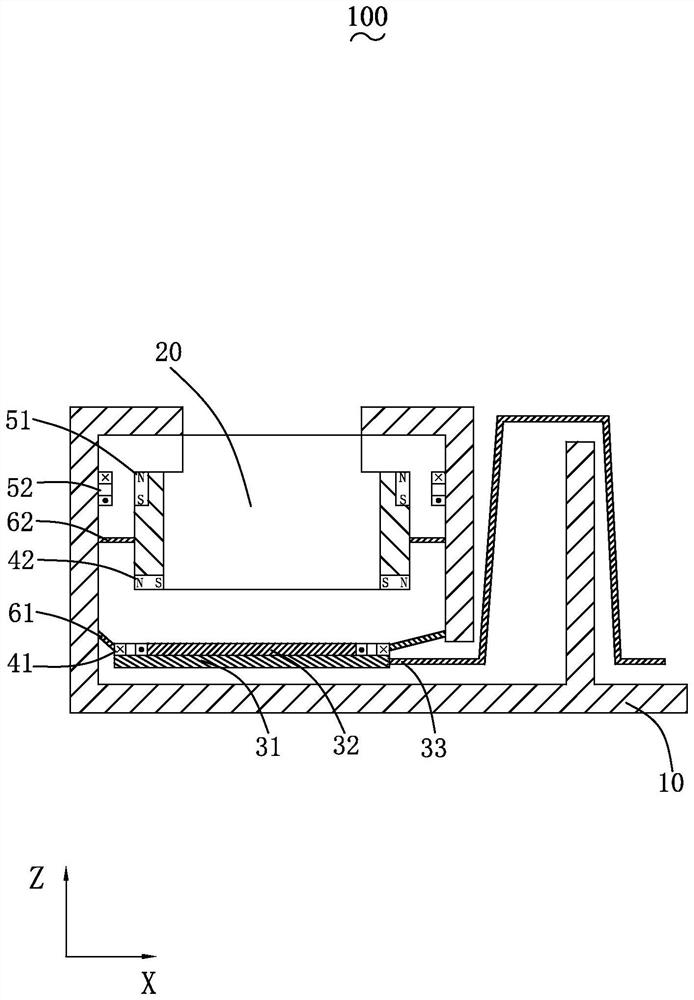
[0030] Figure 1-2 For the first embodiment of the present invention, please also refer to Figure 1-2 , a lens module 100 includes a housing 10 with a housing space, a lens 20 accommodated in the housing space 10, a sensor assembly 30, a driving device 40, and an elastic connector 61, wherein the sensor assembly 30 and the lens 20 are arranged opposite to the lens 20 along the optical axis direction of the lens 20, and the elastic connecting member 61 connec...


PUM


Abstract

The invention provides a lens module, which comprises a shell with an accommodating space, a lens accommodated in the accommodating space, a sensor assembly and a driving device, and is characterizedin that the sensor assembly is movably accommodated in the accommodating space and is arranged opposite to the lens along the optical axis direction of the lens; the driving device drives the sensor assembly to move relative to the lens along / around the optical axis or along the direction perpendicular to the optical axis. Compared with the prior art, the above lens module increases the degree offreedom of jitter compensation by moving the image sensor, i.e., compensates the jitter rotating around the optical axis, thereby improving the optical anti-jitter effect. The driving device directlydrives the image sensor to move, the structure is simple, and the occupied space is small; the size of the image sensor is small, and the activity space of the sensor assembly reserved in the shell issmall, so that the size of the shell can be reduced, and the axial thickness of the lens module is reduced.

Description

【Technical field】 [0001] The invention relates to the technical field of lens optical imaging, in particular to a lens module. 【Background technique】 [0002] With the development of camera technology, lens modules are widely used in camera devices for various purposes, and the combination of lens modules with various portable electronic devices such as mobile phones, video cameras, computers, etc., is favored by consumers. [0003] The lens module includes an image sensor. When the user uses the above-mentioned portable electronic device to take pictures or record videos, the shaking of the portable electronic device will cause the position of the imaging beam to shift on the photosensitive surface of the image sensor, resulting in blurred photos or videos. Optical anti-shake technology is a technology that compensates for this offset by moving (translation, rotation) the lens module, thereby making the captured photos or videos clearer. [0004] The lens module in the rel...

Claims


Application Information

Patent Timeline
Patent Type & Authority Applications(China)
IPC IPC(8): H04N5/225H04N5/232
CPCH04N23/50H04N23/55H04N23/687
Inventor 陶泽李杨
Owner CHANGZHOU RAYTECH OPTRONICS CO LTD
Learn More