
Tool for machining motor shell

A technology for motor casings and machine tools, which is applied in the direction of electromechanical devices, manufacturing motor generators, electrical components, etc., and can solve problems such as low positioning accuracy

Active Publication Date: 2020-11-17
浙江震环数控机床股份有限公司
View PDF5 Cites 2 Cited by
  • Summary
  • Abstract
  • Description
  • Claims
  • Application Information

AI Technical Summary

Problems solved by technology

[0006] In view of the related technologies mentioned above, the inventor believes that there is a defect that the inner hole of the stator is a tapered hole and the positioning accuracy is low

Method used


Image

  • Tool for machining motor shell
  • Tool for machining motor shell
  • Tool for machining motor shell

Examples


Embodiment Construction

[0064] The following is attached Figure 1-9The application is described in further detail.

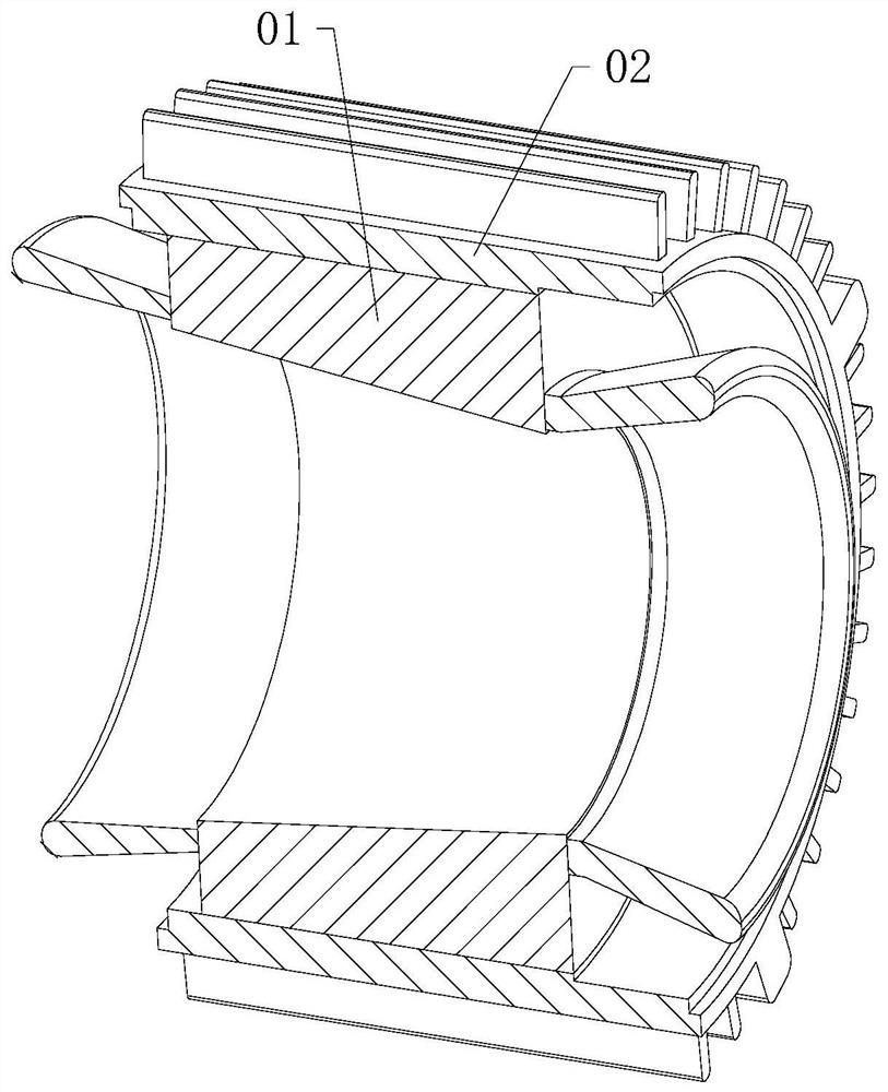
[0065] The conical rotor motor is mainly composed of a shell, a stator, a rotor, a machine cover and other accessories, and the inner hole of the stator and the outer circumference of the rotor are conical. Among them, refer to figure 1 , the stator 01 is pressed into the housing 02 by means of interference fit to form a product.

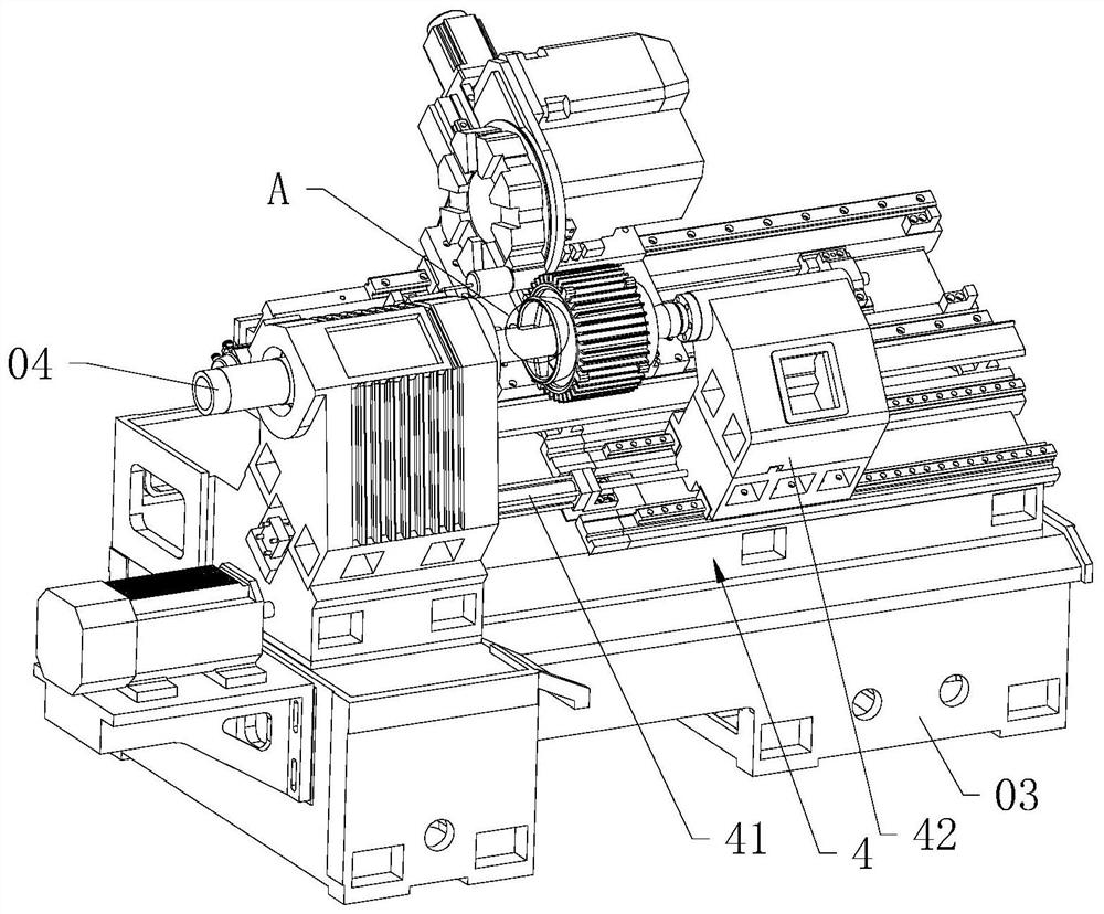
[0066] refer to figure 2 , the CNC machine tool includes a bed 03 and a spindle 04, one end of the spindle 04 is used to connect the motor, and the power transmission between the spindle 04 and the motor can be realized by belt transmission.

[0067] The embodiment of the present application discloses a tool for machining a motor casing.

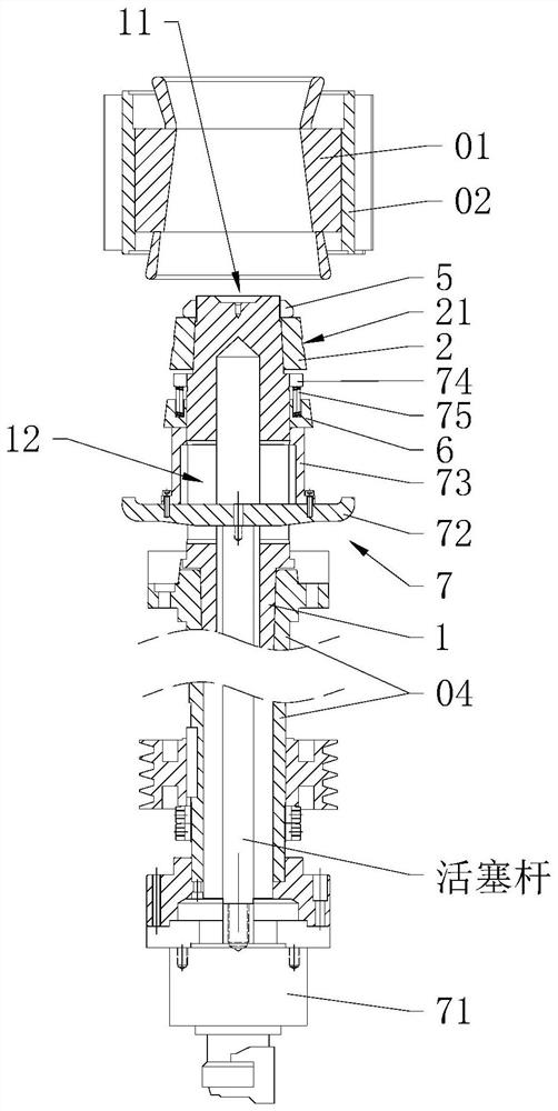
[0068] refer to image 3 , 4 , The tooling for machining the motor shell includes a base shaft 1 , a fixed cone ring 2 , a pressure plate 3 and a clamping driver 4 .

[0069] refer to image 3 , 5 , the base sha...


PUM


Abstract

The application relates to a tool for processing a motor casing, which comprises a base shaft, a fixed conical ring, a movable conical ring, a positioning driving piece, a pressure plate and a clamping driving part, the periphery of the fixed conical ring is used for abutting against the inner wall of one end with smaller diameter of a stator inner hole, and the periphery of the movable conical ring is used for abutting against the inner wall of one end with larger diameter of the stator inner hole; and the clamping driving part is used for driving the pressing disc to abut against the product, so that the inner hole wall of the stator abuts against the periphery of the fixed conical ring, and positioning and clamping are achieved. The axis of the stator coincides with the axis of the baseshaft, positioning and clamping of a product are completed, then positioning and clamping are completed with the axis of the inner hole of the stator as the reference, and the effect of accurate clamping is achieved.

Description

technical field [0001] The present application relates to the field of motor production, in particular to a tooling for motor casing processing. Background technique [0002] Motor (English: Electric machinery, commonly known as "motor") refers to an electromagnetic device that realizes the conversion or transmission of electric energy according to the law of electromagnetic induction. , [0003] The conical rotor motor is mainly composed of a shell, a stator, a rotor, a machine cover and other accessories, and the inner hole of the stator and the outer circumference of the rotor are conical. The conical rotor motor has the ability of self-braking in case of power failure, and is widely used in lifting equipment such as electric hoists and winches. [0004] The stator is pressed into the casing by means of interference fit, and the rotor is embedded in the inner hole of the stator, and the two ends of the rotor can be connected to the cover through bearings, and the cover ...

Claims


Application Information

Patent Timeline
Patent Type & Authority Applications(China)
IPC IPC(8): H02K15/14H02K15/02
CPCH02K15/02H02K15/14
Inventor 宋春燕金翼
Owner 浙江震环数控机床股份有限公司
Learn More